Thermal control instrument mounting mechanism for thermal control of power plant

An installation mechanism and thermal control technology, applied in the direction of supporting machines, mechanical equipment, engine components, etc., can solve the problems of affecting efficiency, long maintenance time, inconvenience, etc., and achieve the effect of maintaining stability, fast installation, and high efficiency

Pending Publication Date: 2021-12-07
广州伶刻尔斯机电有限公司
View PDF5 Cites 0 Cited by
  • Summary
  • Abstract
  • Description
  • Claims
  • Application Information

AI Technical Summary

Problems solved by technology

[0003] In the installation process of some thermal control instruments in the prior art, it needs to be installed on the wall to facilitate the staff to observe and read data, but the commonly

Method used


Image

  • Thermal control instrument mounting mechanism for thermal control of power plant
  • Thermal control instrument mounting mechanism for thermal control of power plant
  • Thermal control instrument mounting mechanism for thermal control of power plant

Examples


Embodiment 1

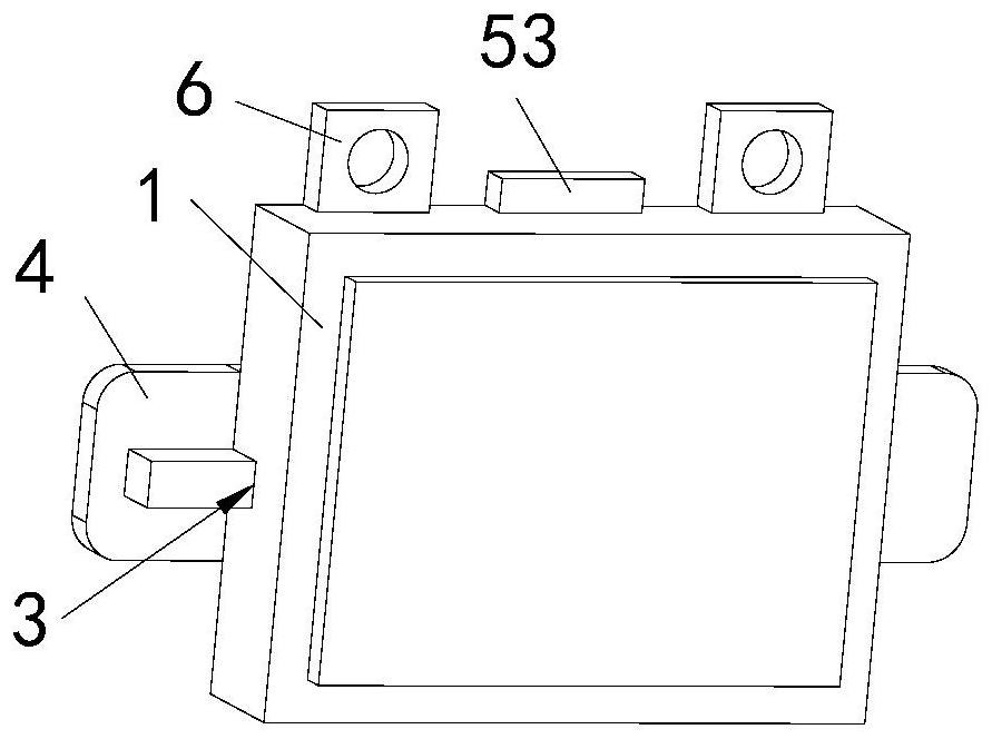
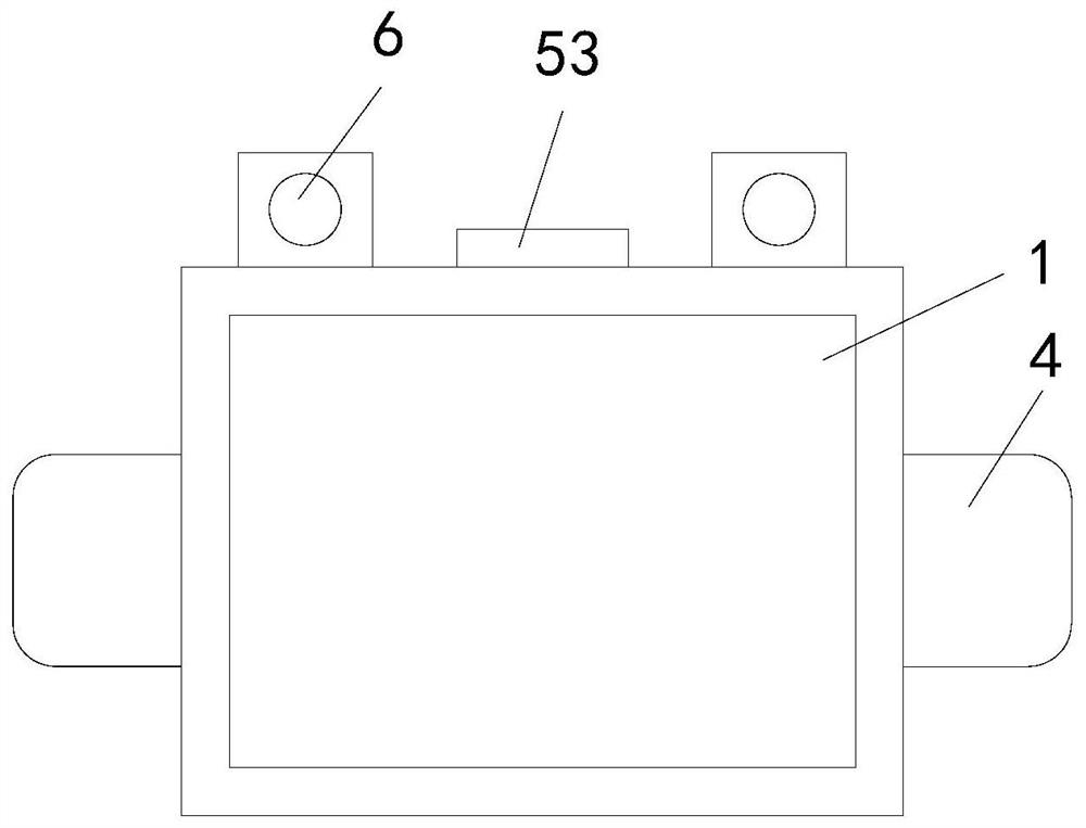
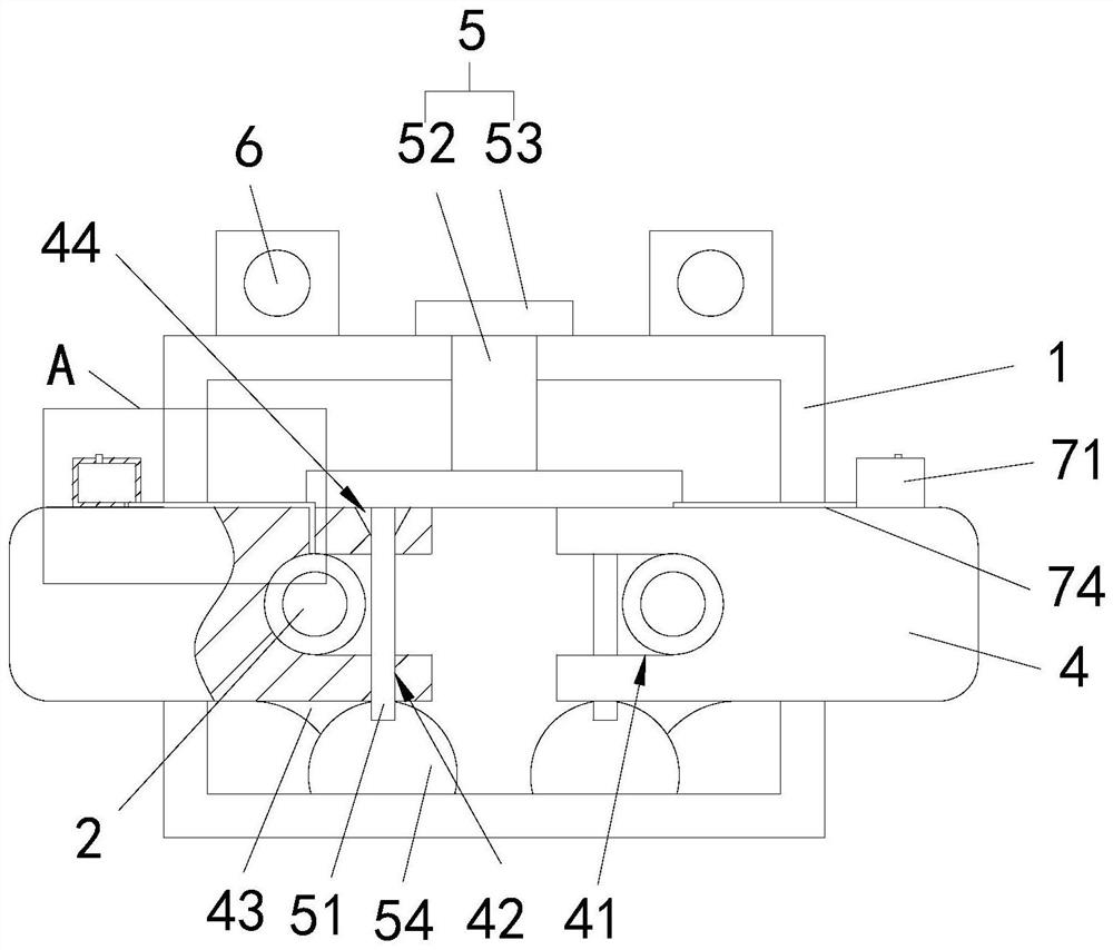
[0034] A thermal control instrument installation mechanism for thermal control in a power plant, comprising a thermal control instrument 1, and corresponding mounting nails 2 are arranged on the wall, and an installation groove 3 is arranged on the back of the thermal control instrument 1, and the installation groove 3 A mounting block 4 is slidably arranged, and a groove 41 corresponding to the mounting nail 2 is provided on one side of the mounting block 4;

[0035] A lubricating mechanism 7 is provided on the top surface of the mounting block 4 , and the lubricating mechanism 7 is used to lubricate the contact portion of the mounting nail 2 with the groove 41 .

[0036] Further, the installation slots 3 and the installation blocks 4 are arranged in pairs, and are arranged symmetrically on both sides of the back of the thermal control instrument 1 .

[0037] Further, the back of the thermal control instrument 1 is also provided with a locking mechanism 5, the side wall of th...

Embodiment 2

[0045] The present invention adds lubricating mechanism 7 on the basis of embodiment one; Specifically as follows:

[0046] Further, the lubricating mechanism 7 includes a lubricating box 71, the top of the lubricating box 71 is provided with an oil filling port 77, the bottom of the lubricating box 71 is provided with an oil outlet 72, and the mounting block 4 is provided with a fine hole 73, A capillary 74 is perforated in the thin hole 73 , one side of the capillary 74 faces the contact between the mounting nail 2 and the groove 41 , and the other side is inserted into the oil outlet 72 and communicates with the inside of the lubricating box 71 .

[0047] Further, a lubricating groove 75 is arranged around the inner surface of the groove 41 , and a lubricating strip 76 is arranged outside the lubricating groove 75 , and the area of ​​the lubricating strip 76 is larger than that of the lubricating groove 75 .

[0048] By adopting the above-mentioned technical scheme, the lub...


PUM


Abstract

The invention relates to a thermal control instrument mounting mechanism for thermal control of a power plant. The mechanism comprises a thermal control instrument, corresponding mounting nails are arranged on a wall surface, a mounting groove is formed in the back surface of the thermal control instrument, a mounting block is arranged in the mounting groove in a sliding manner, and grooves corresponding to the mounting nails are formed in one side of the mounting block. A lubricating mechanism is arranged on the top surface of the mounting block and is used for lubricating the contact parts of the mounting nails and the grooves. When overhauling and dismounting are needed, only a locking mechanism needs to be pulled out, then the mounting block is pulled out from the two sides, and then dismounting can be completed, so that mounting and dismounting can be rapidly carried out during overhauling, and the efficiency is high. The lubricating mechanism is arranged to lubricate the contact parts of the mounting nails and the grooves, so that the effect of preventing the mounting nails and the groove surfaces from rusting due to long time is achieved, and subsequent disassembly and maintenance of the thermal control instrument are facilitated.

Description

technical field [0001] The invention relates to the technical field of thermal control installation, in particular to a thermal control instrument installation mechanism for thermal control in a power plant. Background technique [0002] An automation instrument is an automation technology tool with relatively complete functions, which is composed of a number of automation components. It generally has several functions at the same time, such as measurement, display, recording or measurement, control, alarm, etc. The automation instrument itself is a system, but also a subsystem in the whole automation system. Automatic instrument is a kind of "information machine". Its main function is the conversion of information form, converting input signal into output signal. The signal can be expressed in time domain or frequency domain, and the transmission of signal can be modulated into continuous analog or intermittent. Continuing digital form. [0003] In the installation proce...

Claims


Application Information

Patent Timeline
IPC IPC(8): F16M13/02F16M11/04F16N7/12F16N31/02
CPCF16M13/02F16M11/04F16N7/12F16N31/02
Inventor 李美容
Owner 广州伶刻尔斯机电有限公司
Why Eureka
Try Eureka