Electric vehicle with secondary battery power storage system

a secondary battery and power storage system technology, applied in the direction of secondary cell service/maintenance, battery/fuel cell control arrangement, propulsion by batteries/cells, etc., can solve the problem of inconvenient application of nickel-cadmium batteries and nickel-metal hydride batteries, whose residual capacity cannot be determined, and the electrolyte is dried or increased in internal pressur

Inactive Publication Date: 2000-03-07
HITACHI LTD
View PDF6 Cites 56 Cited by
  • Summary
  • Abstract
  • Description
  • Claims
  • Application Information

AI Technical Summary

Problems solved by technology

Since the variation of the voltage of nickel-metal hydride batteries, as compared with that of nickel-cadmium batteries, in the final stage of charging is obscure, nickel-metal hydride batteries may be overcharged causing drying of the electrolyte or increase in the internal pressure and entailing safety problems unless nickel-hydrogen batteries are charged after due consideration of the discharge capacity.
Although a method of managing the residual voltage on the basis of the voltage is effective when applied to lead-acid batteries and lithium batteries the voltage of which varies comparatively widely during charging and discharging, the same is unsuitable for application to nickel-cadmium batteries and nickel-metal hydride batteries the residual capacity of which cannot be determined on the basis of only the voltage.
It is difficult to predict the residual capacity accurately on the basis of current and temperature or on the basis of time besides on the basis of voltage under operating condition where discharge rate changes.
When managing the residual capacity of a battery on the basis of measured internal resistance or capacitance, it is difficult to determine whether the increase of the internal resistance is due to the deterioration of the battery or whether the increase o

Method used


Image

  • Electric vehicle with secondary battery power storage system
  • Electric vehicle with secondary battery power storage system
  • Electric vehicle with secondary battery power storage system

Examples


Embodiment Construction

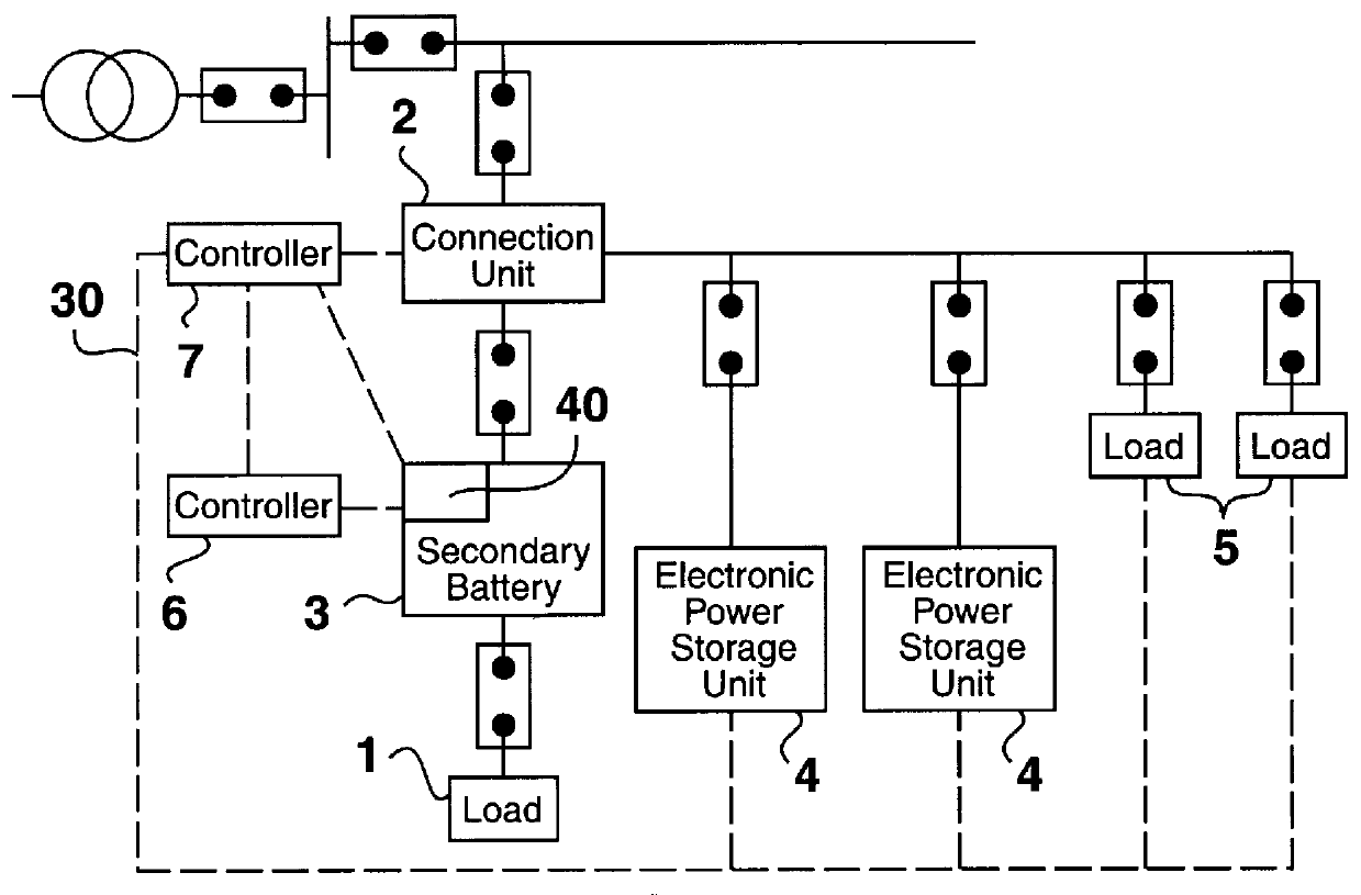
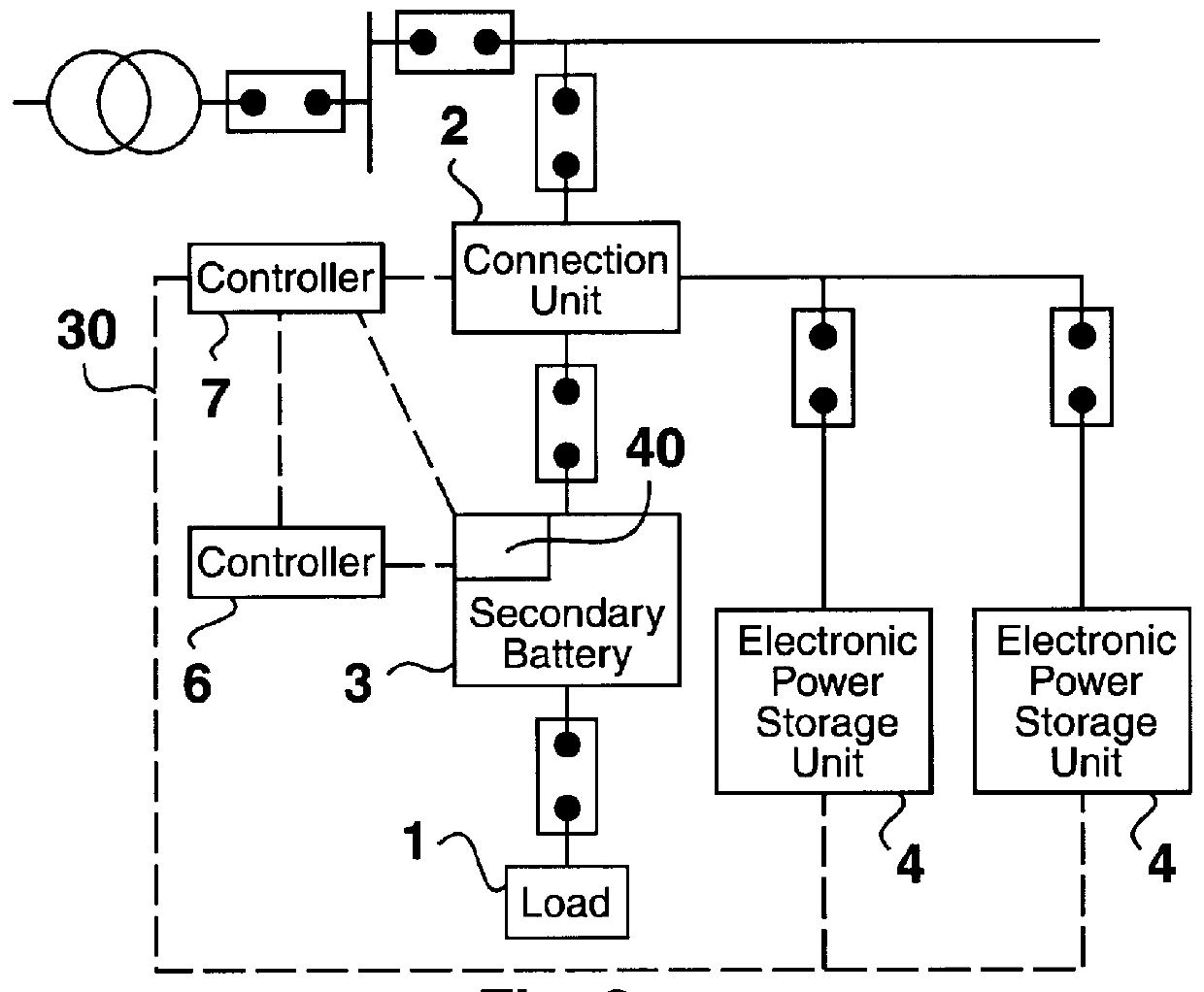
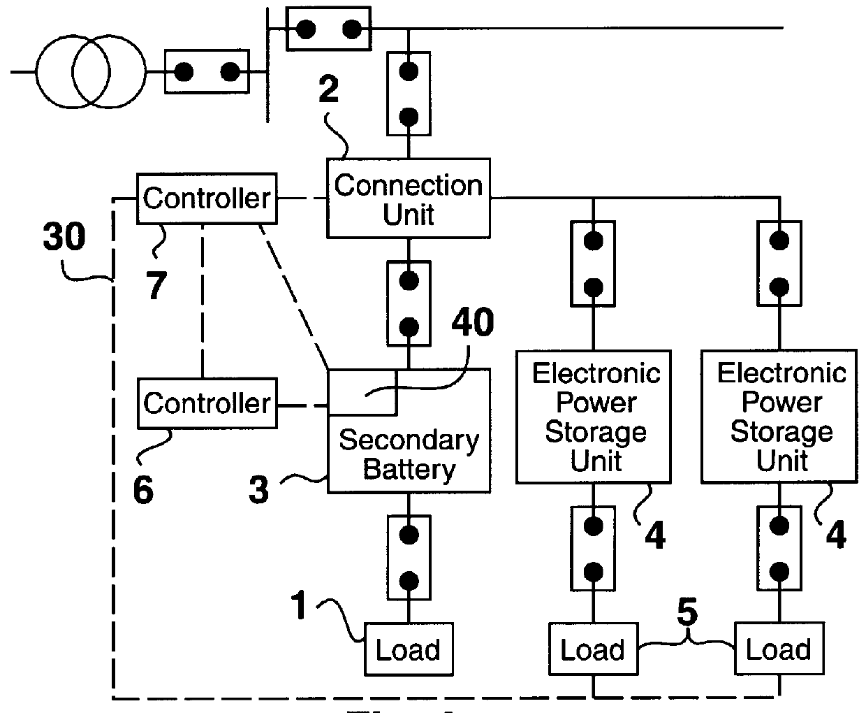
In a secondary battery electric power storage system in a comparative example 1, a secondary battery load 1 and a connection unit 2 are connected to a secondary battery 3. The secondary battery 3 is connected to the connection unit 2 and the secondary battery 3 is charged with night period rate electric power. Then, the secondary battery 3 is connected to the secondary battery load 1 and the electric power stored in the secondary battery 3 is discharged into the secondary battery load 1. After discharging, the secondary battery 3 is disconnected from the secondary battery load 1 and is connected to the connection unit 2 to charge the secondary battery 3 with night period rate electric power. The residual capacity of the secondary battery is determined by subtracting a discharged capacity from an initial capacity. FIG. 9 shows the difference between residual capacity indication and actual residual capacity. As is obvious from FIG. 9, the difference increases as the number of charge a...


PUM


Abstract

The present invention provides a distributed secondary battery type power storage system capable of maintaining the soundness of the secondary battery and of efficient electric power charging and discharging operations. The secondary battery power storage system comprises a secondary battery connected to a load, a charge/discharge unit connectable to a power system and connected to the secondary battery, and a plurality of loads connected to the charge/discharge unit. A power receiving object is selected and a capacity is determined on the basis of information about the operating condition of the plurality of loads, and the surplus electric power remaining in the secondary battery after feeding electric power from the secondary battery to the load is fed to the selected power receiving object through the charge/discharge unit. The secondary battery power storage system is capable of maintaining the soundness of the secondary battery and of efficient charging and discharging operation.

Description

BACKGROUND OF INVENTIONField of InventionThe present invention relates to a secondary battery electric power storage system and, more particularly, to a battery system which is prouided with evaluation meams of the soundness and the residual power of a battery, the distribution of the surplus electric power of a battery, and the optimum charge / discharge control of a battery. Most secondary batteries for automobiles, uninterrupted power supplies and the like have been lead-acid batteries.The diffusion of electric power storage systems and electric vehicles, and the development of secondary batteries capable of storing electric power in a high energy density have been strongly desired to meet rising necessity for the leveling of power demand and progressively increasing demand for global environmental protection, and the development of new batteries has been expected.Various kinds of large-capacity secondary batteries including nickelcadmium batteries, nickel-metal hydride batteries, ...

Claims


Application Information

Patent Timeline
IPC IPC(8): H02J3/32H02J3/28H02J7/00H02J13/00H02J7/34H01M10/44H01M10/48H02J7/10
CPCB60L11/1864H02J3/32H02J7/0004H02J7/0022H02J7/0063H02J7/34H02J13/0003Y02E60/721Y02T10/7005Y02T10/7055Y02T10/7061Y04S10/126B60L58/21H02J7/00036H02J13/00034H02J7/00047Y02T10/70H02J13/00016Y04S40/124Y02B90/20Y02T90/167Y02E60/10Y02E60/00B60L50/50H02J7/00
Inventor IKAWA, KYOKOHORIBA, TATSUO
Owner HITACHI LTD
Why Eureka
Try Eureka