Retention mechanism for catheter with distal anchor

Inactive Publication Date: 2000-03-28
BOSTON SCI CORP
View PDF10 Cites 53 Cited by
  • Summary
  • Abstract
  • Description
  • Claims
  • Application Information

AI Technical Summary

Problems solved by technology

Also these catheters generally have side ports at the distal end that can be inadvertently drawn into the abdominal cavity creating potential for severe infections when the catheter is inserted for bladder treatment.
The assembly of such mechanisms, particularly when it is desired to maintain a sealed environment, introduces complicated pr

Method used


Image

  • Retention mechanism for catheter with distal anchor
  • Retention mechanism for catheter with distal anchor
  • Retention mechanism for catheter with distal anchor

Examples


Embodiment Construction

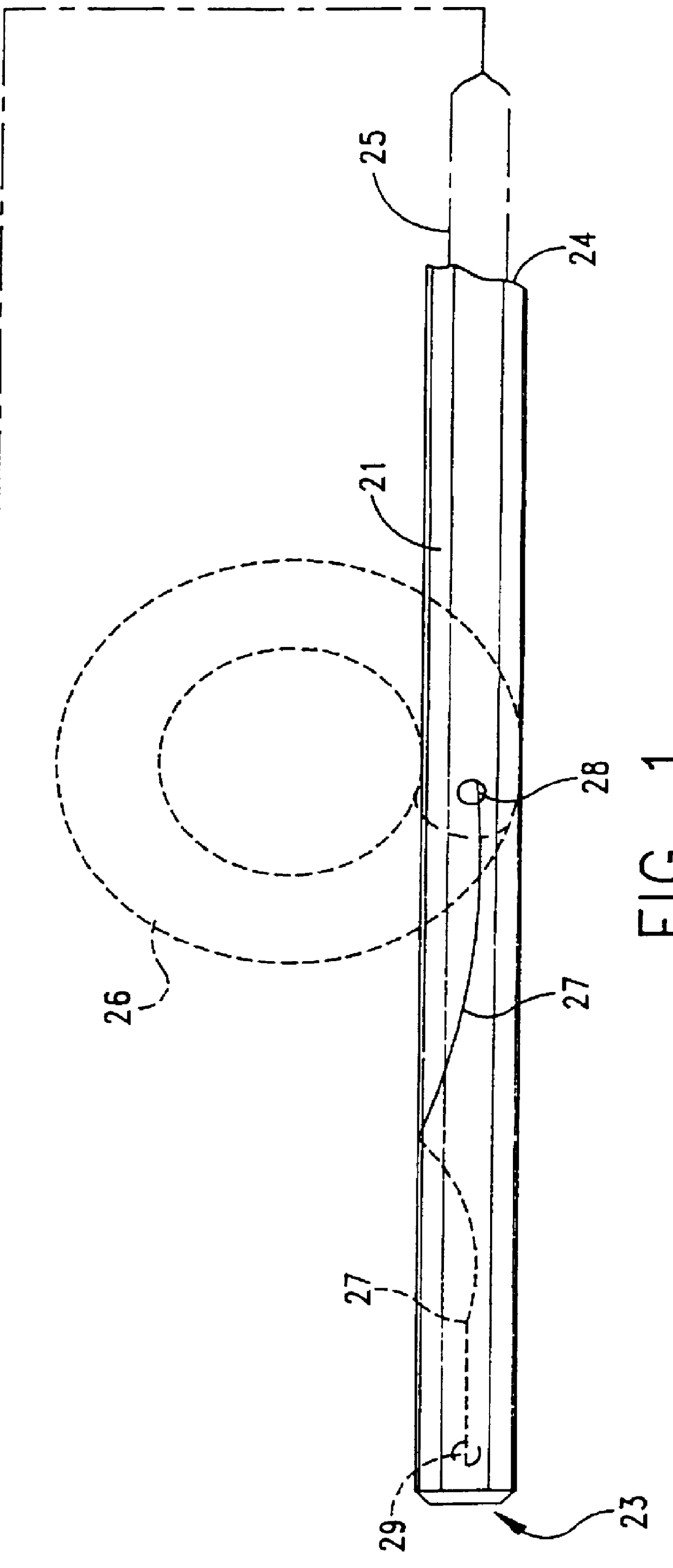
FIG. 1 depicts a catheter 20 with a radially flexible tube 21 that extends between a proximal end 22 and a distal end 23. A lumen 24 extends through the tube 21 and carries a flexible link 25 in the form of one or more suture threads. As shown by the solid lines in FIG. 1, the tube 21 extends along an axis when it is inserted and deflects into,a pigtail loop 26 as shown by the dashed lines in FIG. 1 when a cannula or other straightening implement is removed from the lumen 24.

A distal end portion 27 of the suture thread 25 extends through a draw port or aperture 28 displaced from the distal end 23 and a draw port 29 or other connection at the distal end 23. If the suture thread 25 is loose when the pigtail loop formed, straightening the loop will draw additional suture thread to the space between the draw ports 28 and 29. After the pigtail loop 26 reforms, as known in the art, at least some of the additional suture thread must be withdrawn proximally to prevent forces from completely...


PUM


Abstract

A mechanism for use with an anchoring structure of a drainage catheter. A suture thread as a flexible link extends from the distal end of a catheter through the catheter lumen to the mechanism at the proximal end of the catheter. The mechanism includes a distal body affixed to the proximal end of the catheter and a proximal body that can be displaced axially with respect to the distal body between clamping and unclamped positions. In a clamped position, the bodies clamp the suture thread to prevent inadvertent displacement of the suture thread. Displacement of the proximal body in certain embodiments takes up slack in the suture thread generated when the anchor forms.

Description

1. Field of the InventionThis invention generally relates to the field of catheters and more particularly to a catheter having a mechanism for retaining a distal end of the catheter in a predetermined configuration.2. Description of Related ArtThere are a variety of therapies or treatment modalities that require a catheter with a distal anchor or the like to retain the catheter in position. One particular application involves catheters used for drainage purposes. For example, procedures for the suprapubic catheterization of the bladder drain the bladder after surgery or when the genitourinary system is plugged by an obstruction. Procedures using other percutaneously inserted catheters are also used to drain the kidney or biliary system as well as to drain abscesses, other sites of fluid collection and other viscera. Still other procedures use percutaneously inserted catheters as gastrostomy feeding tubes.Generally these catheters are introduced into a patient through a large hypoder...

Claims


Application Information

Patent Timeline
IPC IPC(8): A61M25/02A61M25/04A61M25/01
CPCA61M25/0105A61M25/04
Inventor CHU, MICHAEL S. H.CHIN, YEM
Owner BOSTON SCI CORP
Why Eureka
Try Eureka