Belleville spring

Inactive Publication Date: 2000-08-15
BARNES GROUP
View PDF9 Cites 23 Cited by
  • Summary
  • Abstract
  • Description
  • Claims
  • Application Information

AI Technical Summary

Benefits of technology

Another object of the present invention is the provision of a Belleville spring and method of making a Belleville spring, which reduces the s

Problems solved by technology

Since the Belleville spring is formed by forceably coiling a straight, thin strip of spring steel into the circular shaped body, the spring is not produced by th

Method used


Image

  • Belleville spring
  • Belleville spring
  • Belleville spring

Examples


Embodiment Construction

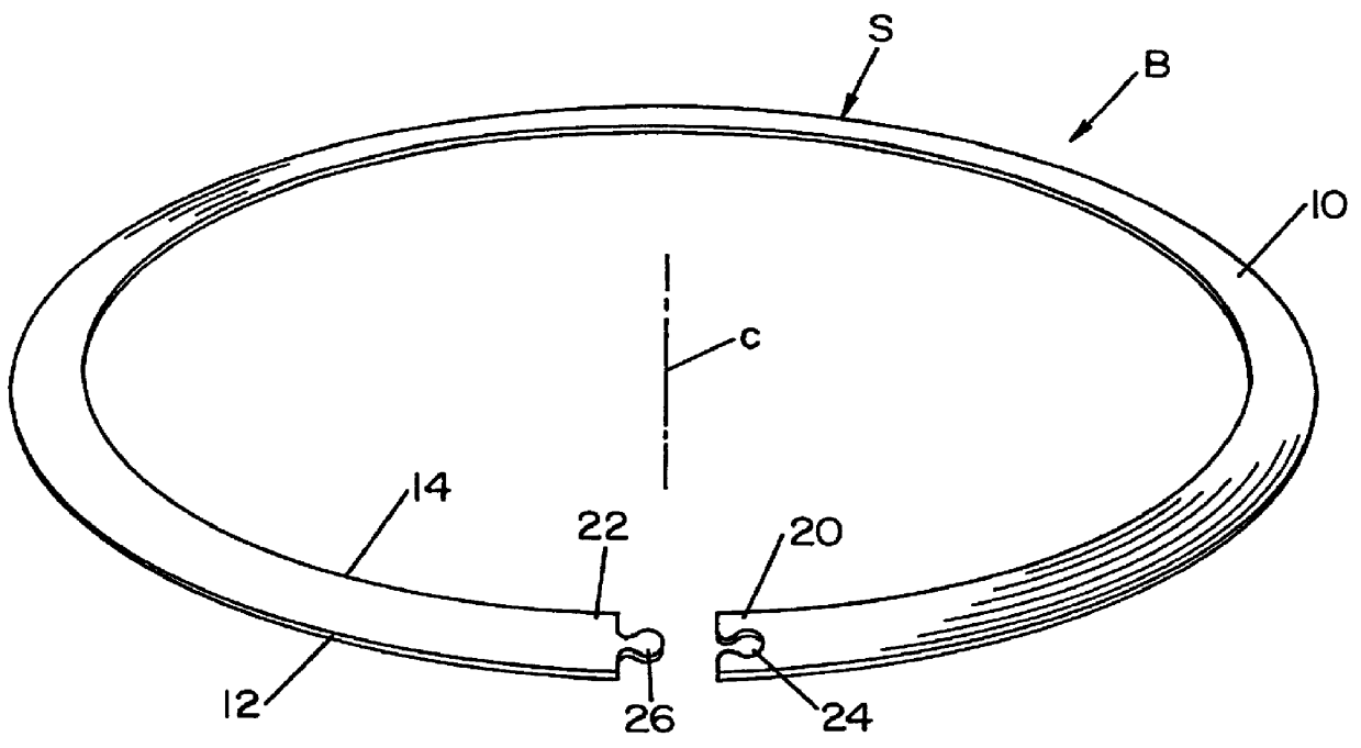
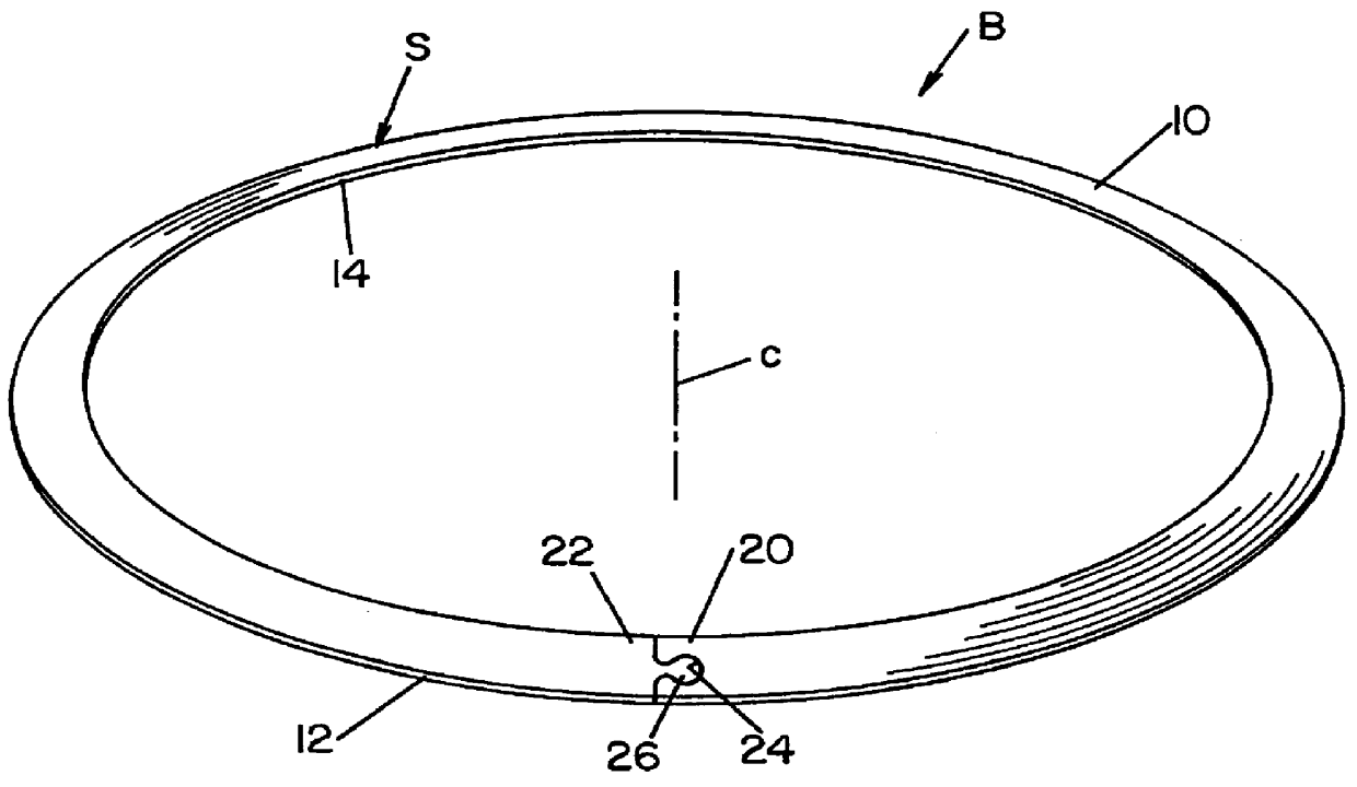
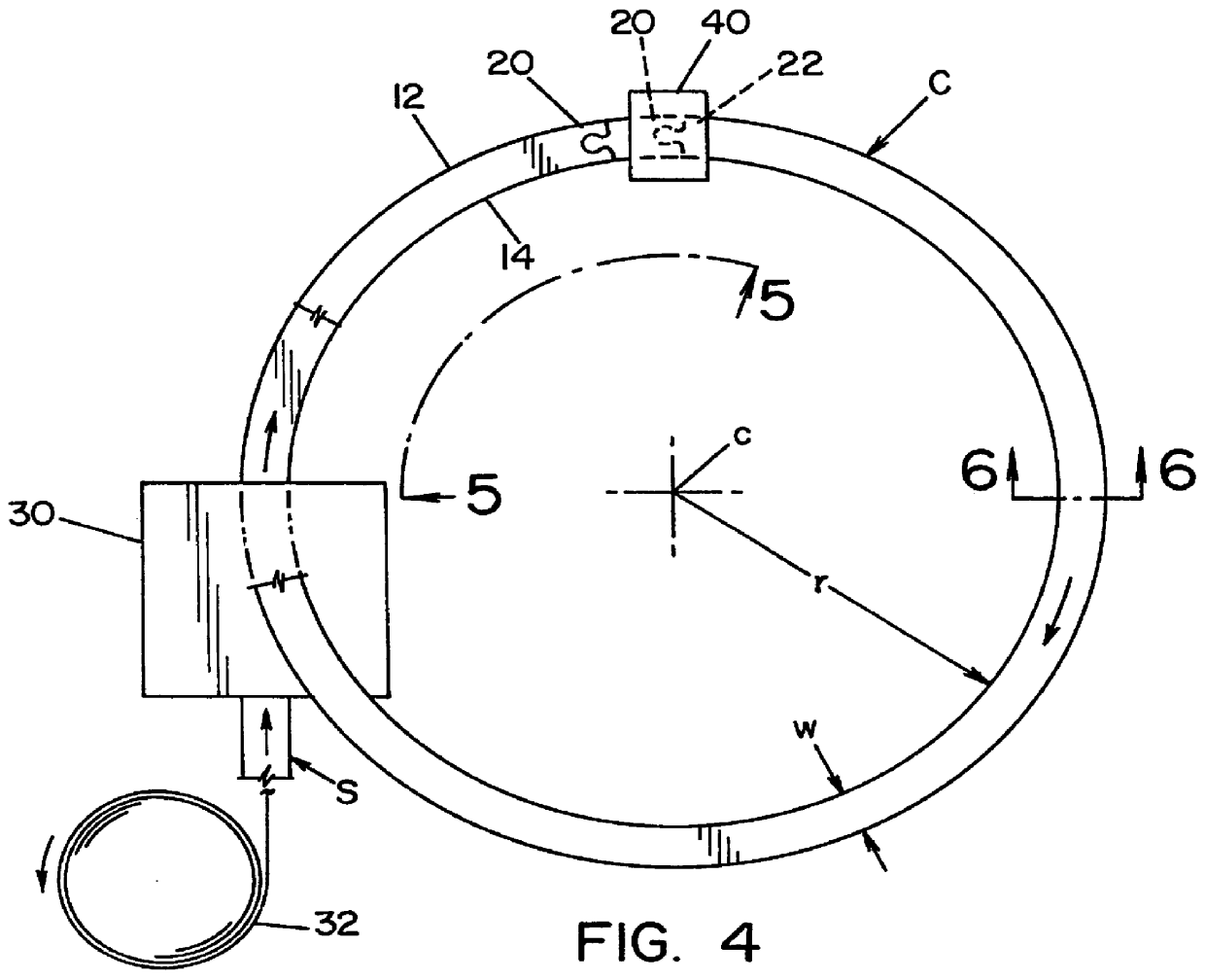
Referring now to the drawings wherein the showings are for the purpose of illustrating preferred embodiments of the invention only, and not for the purpose of limiting same, FIG. 1 illustrates a Belleville spring B, in the form of a circular body 10 formed from coiled, hardened spring steel strip S having free ends 20, 22 with interlocking or dovetail elements, illustrated as female element 24 and male element 26. In use of the Belleville spring, the free ends are interlocked or held together by elements 24, 26 to form the frusto-conical configuration of a Belleville spring, as shown in FIG. 2. This spring is used in the same applications of any Belleville spring. It is not necessary to securely affix the interlocking or dovetail elements; however, these elements can be fixed by welding, adhesion or otherwise. When Belleville spring B has been constructed in accordance with the present invention it has the side profile illustrated in FIG. 3. The spring B is frusto-conical in configu...


PUM

PropertyMeasurementUnit
Diameteraaaaaaaaaa
Tensionaaaaaaaaaa

Abstract

A Belleville spring comprising a thin strip of hardened spring steel coiled into a circular shaped body with a frusto-conical configuration having an inner diameter and an outer diameter, wherein the strip has two free ends and the coiled spring steel body has the free ends joined together.

Description

This application relates to the art of Belleville springs and more particularly to a novel Belleville spring and the method used for producing such spring.BACKGROUND OF INVENTIONSprings of the Belleville type have been used for various applications and constitute circular elements of spring steel having a generally frusto-conical shape with an inner periphery which is spaced axially from the plane of the outer spring periphery so that the force applied axially against the spring causes the inner periphery to move toward the outer periphery to place the spring under compression. This movement of the frusto-conical spring steel element in an axial direction causes the spring to generate a restoring force proportional to the applied load, which restoring force is not uniform over the relatively small movement of a frusto-conical spring. Belleville springs are used in many applications and are produced by the millions for a wide variety of mechanical devices, such as transmissions for a...

Claims


Application Information

Patent Timeline
IPC IPC(8): F16F1/02F16F1/32F16B43/00
CPCF16B43/00F16F1/32F16F2226/00Y10T403/7094Y10T403/553Y10T29/49609Y10T29/49611F16B2200/30
Inventor LABESKY, MATTHEW JOHN
Owner BARNES GROUP
Why Eureka
Try Eureka