Flow cytometry apparatus and method

a flow cytometry and flow cytometry technology, applied in the field of flow cytometry, can solve problems such as limitations in the application of flow cytometry

Inactive Publication Date: 2001-07-03
SOFTRAY
View PDF2 Cites 194 Cited by
  • Summary
  • Abstract
  • Description
  • Claims
  • Application Information

AI Technical Summary

Problems solved by technology

As discussed previously, the competing requirements imposed on flow cytometry create an inherent conflict between high sample throughput and high detectivity that has proven most difficult to overcome resulting in limitations in applications for flow cytometry.

Method used


Image

  • Flow cytometry apparatus and method
  • Flow cytometry apparatus and method
  • Flow cytometry apparatus and method

Examples


Embodiment Construction

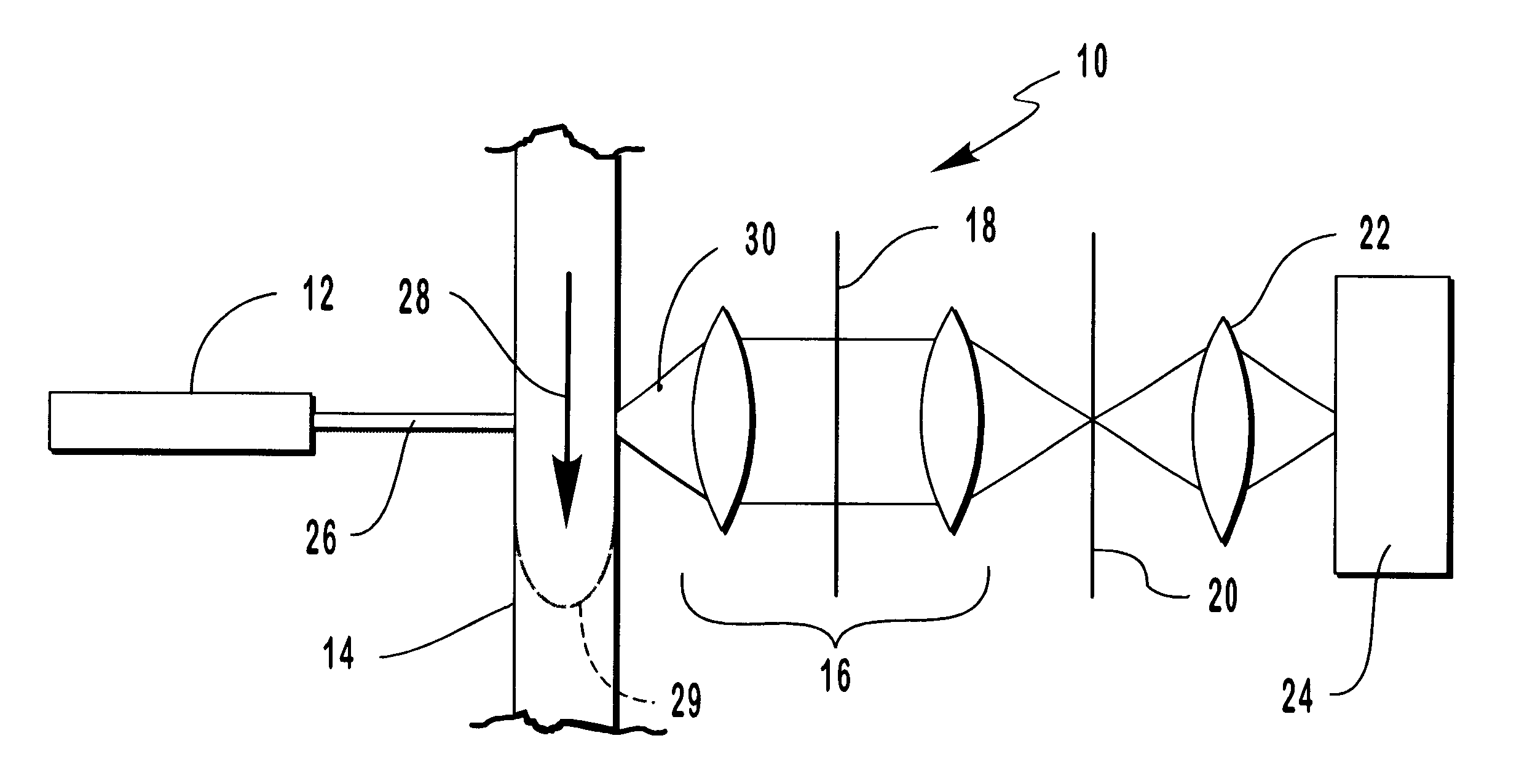
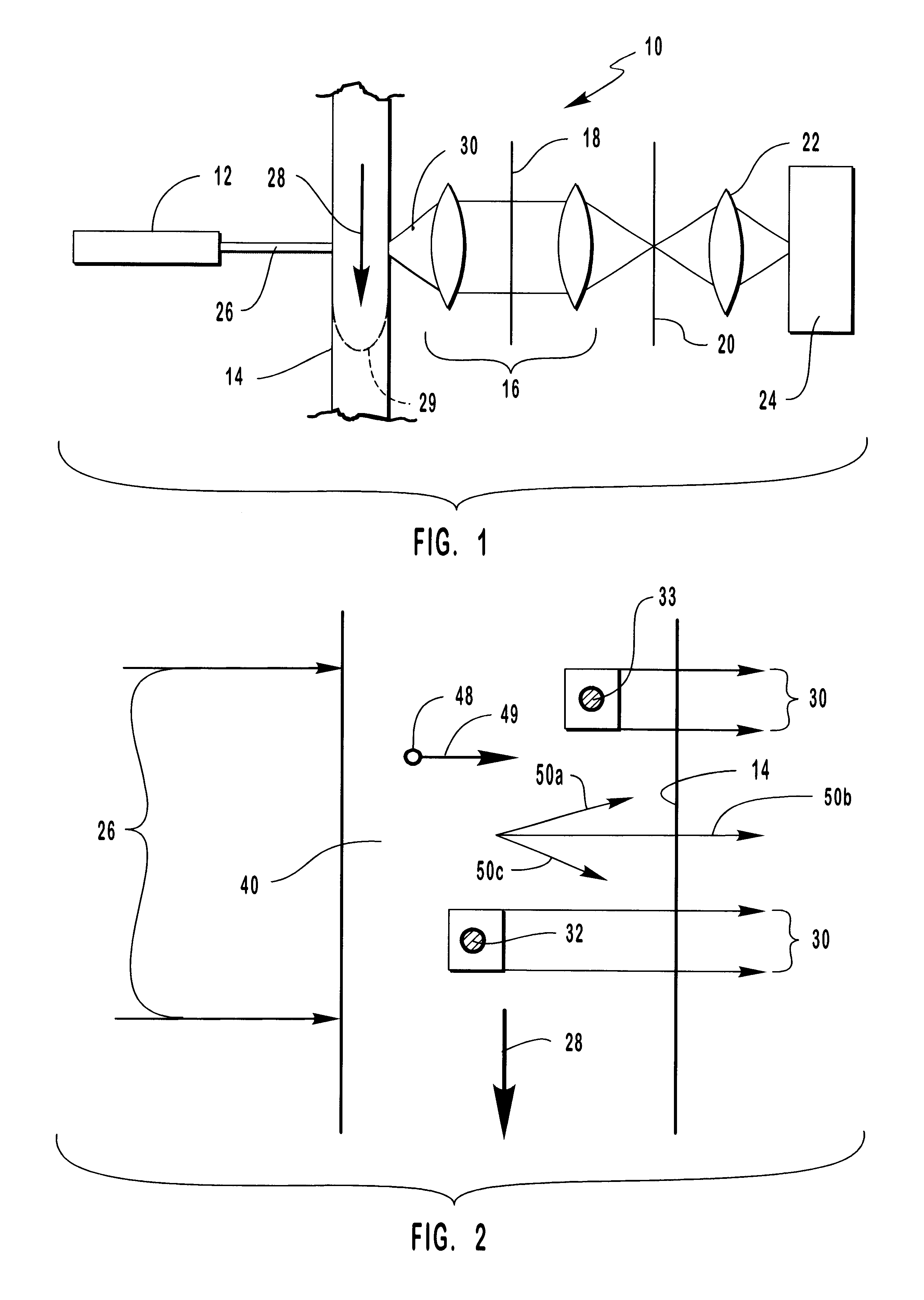
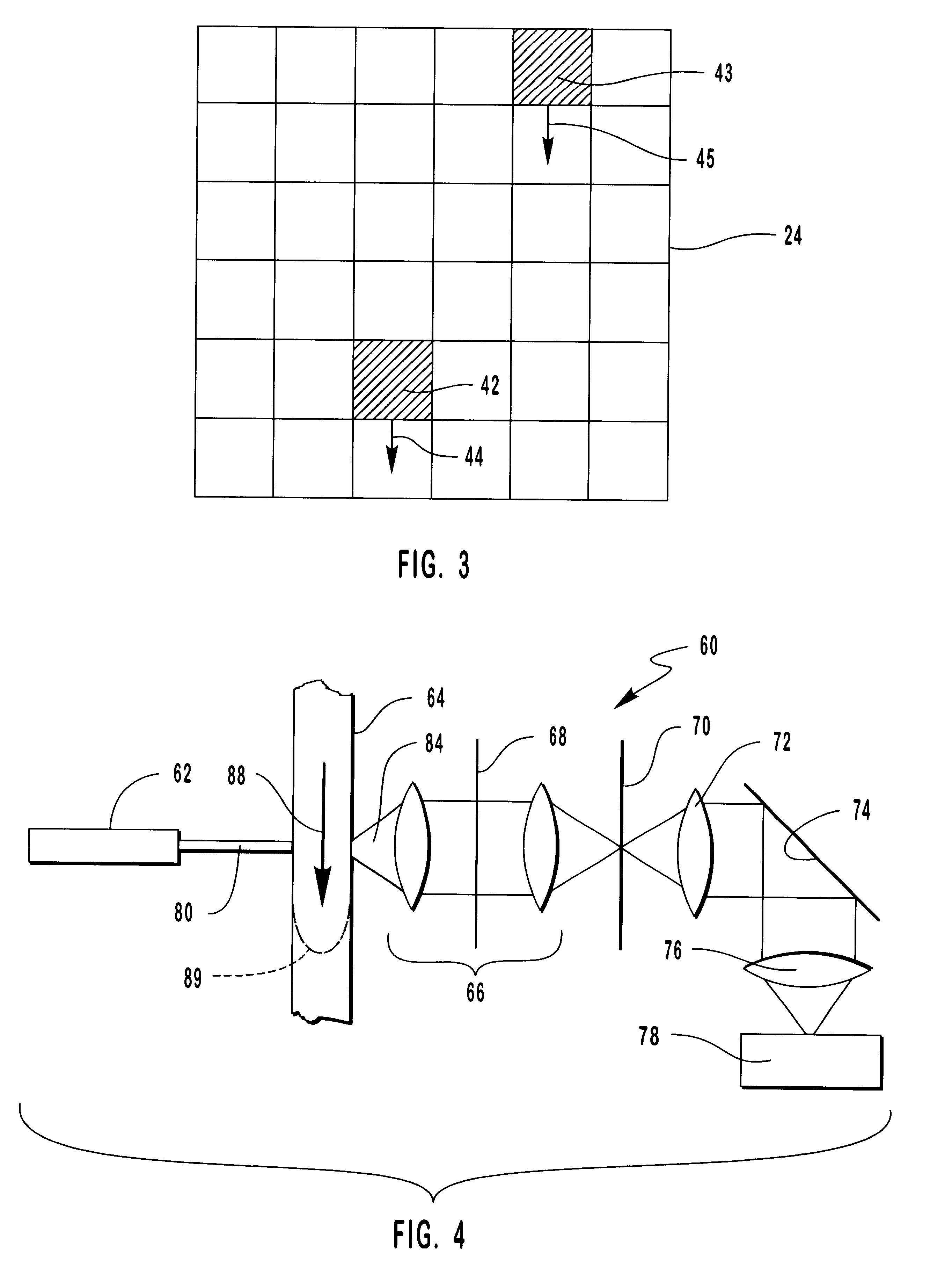
Referring now to FIG. 1, a first preferred embodiment of the novel TDI / CCD flow cytometer of this invention is shown generally at 10 and includes a laser 12, a flow zone 14 having a sample flow 28 passing therethrough, reimaging optics 16 having a notch filter 18 therein, an aperture 20, a focus lens 22 and a CCD 24. Laser 12 emits a laser beam 26 through flow zone 14 to illuminate a first target particle 32 and a second target particle 33 (FIG. 2) therein and to cause the same to fluoresce as fluorescence 30. Fluorescence 30 is optically processed by reimaging optics 16 and notch filter 18 and focused onto a field-of view aperture 20. Focus lens 22 focuses the resultant fluorescence 30 onto CCD 24 (FIG. 3) as will be discussed more fully hereinafter.

Sample flow 28 passes through flow zone 14 and exhibits a typical, parabolic-like flow velocity profile 29 as shown schematically herein by the dashed line in flow zone 14. Flow velocity profile 29 is created as a result of the surface ...


PUM

PropertyMeasurementUnit
lengthaaaaaaaaaa
lengthaaaaaaaaaa
diameteraaaaaaaaaa

Abstract

A flow cytometer for detecting target particles such as microorganisms including biological cells and viruses as well as molecular species. The flow cytometer includes a detection system involving a CCD having a time delay integration capability to thereby increase the signal from the target particle and decrease the noise detected by the CCD. Calibration particles can be included in the sample stream of the flow cytometer for coordinating the readout of the CCD with the rate of flow of the sample stream to improve the detection capability of the CCD. Statistical analysis techniques can also be used to determine the rate of flow of target particles in the sample stream to thereby coordinate the readout rate of the CCD with the rate of flow of the target particles.

Description

1. Field of the InventionThis invention relates to flow cytometry and, more particularly, to an improved flow cytometry apparatus and method involving a novel time delayed integration of a charge coupled device in the detection apparatus for enhancing the signal-to-noise ratio.2. The Prior ArtCytometry is the measurement of the physical and / or chemical characteristics of biological cells. Since the technology of my novel discovery as disclosed and claimed herein can be adapted to other systems such as viruses and molecules as well as biological cells, I have adopted the term "cytometry" to refer to the detection of all of these species which, for the sake of convenience are referred to herein as "target particle(s)." Flow cytometry, as the name implies, involves the delivery of a flowing stream containing a sample having target particles therein to the detection region of a flow cytometer. The target particles in the detection region are irradiated using a laser to create an illumin...

Claims


Application Information

Patent Timeline
Patent Type & Authority Patents(United States)
IPC IPC(8): G01N15/14
CPCG01N15/14
Inventor JOHNSON, PAUL E.
Owner SOFTRAY
Why Eureka
Try Eureka