Spindle in a machine tool

a machine tool and spindle technology, applied in boring/drilling equipment, turning equipment, milling equipment, etc., can solve problems such as damage to segments and malfunctions

Inactive Publication Date: 2002-11-19
OTT JAKOB & SPANNTECHN
View PDF6 Cites 22 Cited by
  • Summary
  • Abstract
  • Description
  • Claims
  • Application Information

AI Technical Summary

Benefits of technology

The second guiding guarantees namely that all segments are always in a defined position, i.e. also and particularly in the two operation positions which correspond to the radial end positions. It that way, it is guaranteed that a new tool holder can always be inserted on defined conditions with its shaft into the receptacle of the spindle and, there, after short locating run of the spindle receptacle with the coupling speed, also the interlocking connection between tenon block and groove can be made, so that the tool holder is not only clamped in the correct angle position, but also a reliable non-positive connection in the region of the conical seat between shaft and receptacle is reached.
This measure has the advantage that a particularly simple sequence of movements is produced, since, for the second guiding, no extra force source or force deviation is required, it is sufficient, rather, if the bushing is supported by the spindle.

Problems solved by technology

In these usual clamping mechanisms, a malfunction can arise due to the fact that the segments, in their radially inner operation position (if the clamping mechanism is released) and in the interpositions between the two operation positions, too, take up undefined positions.
If, then, the segments are with their front end in an undefined position, there may be malfunctions when the next tool holder is inserted.
But then, the usual connection between a tenon block and a groove between receptacle and tool holder cannot act, so that there is no connection between tool holder and spindle that is able to work.
Apart from that, in such undefined situations a damage of the segments may occur.

Method used


Image

  • Spindle in a machine tool
  • Spindle in a machine tool
  • Spindle in a machine tool

Examples


Embodiment Construction

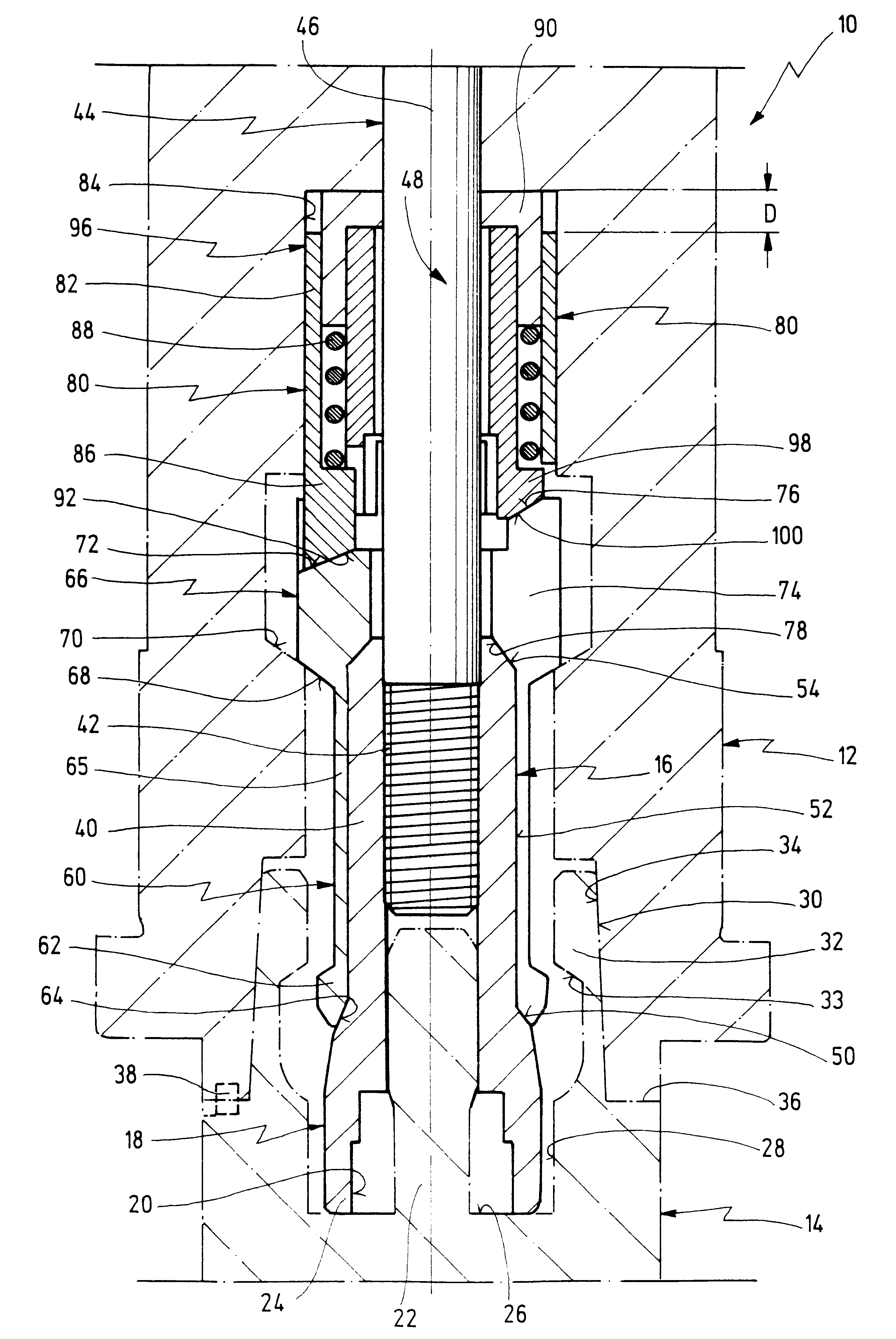
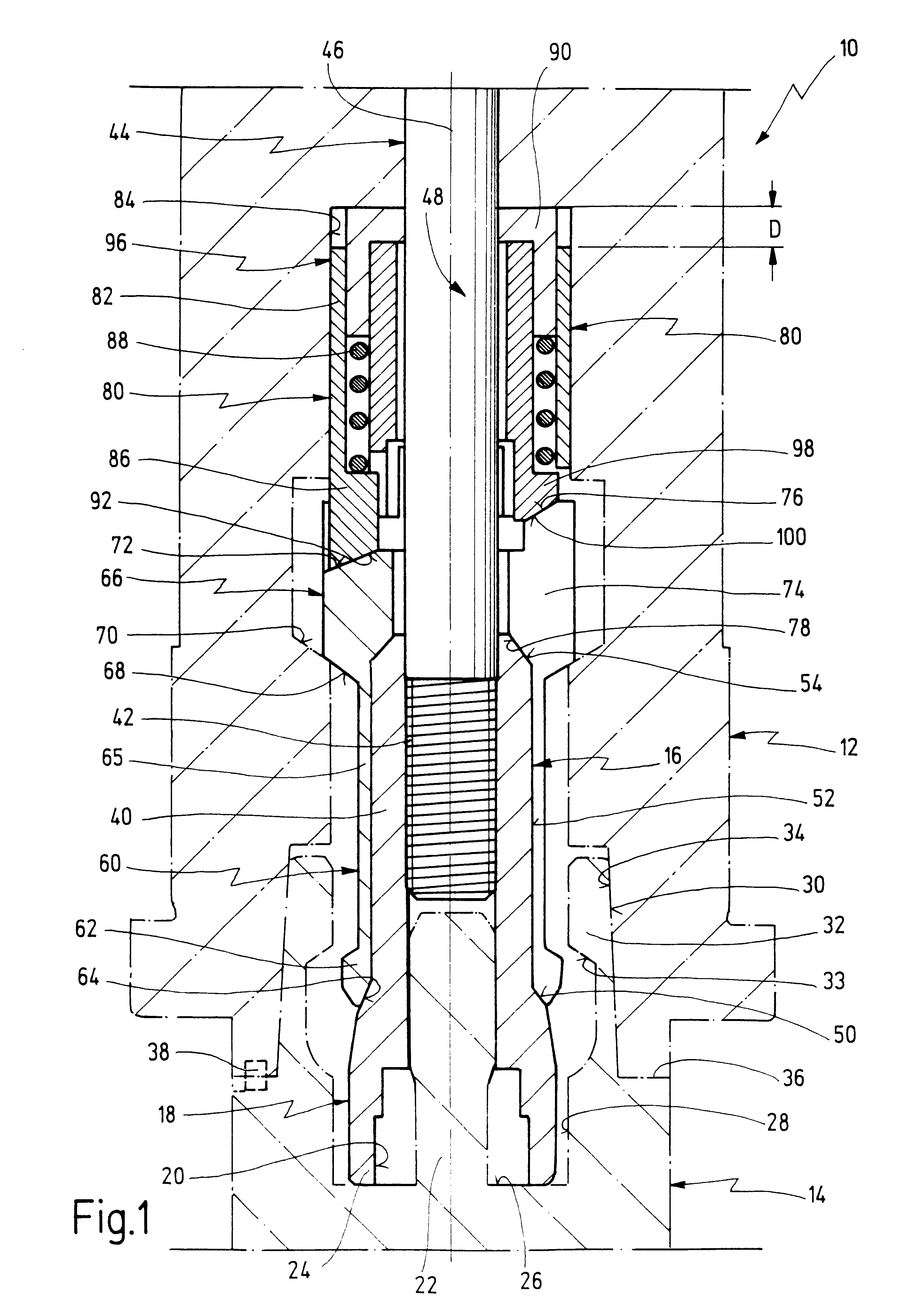
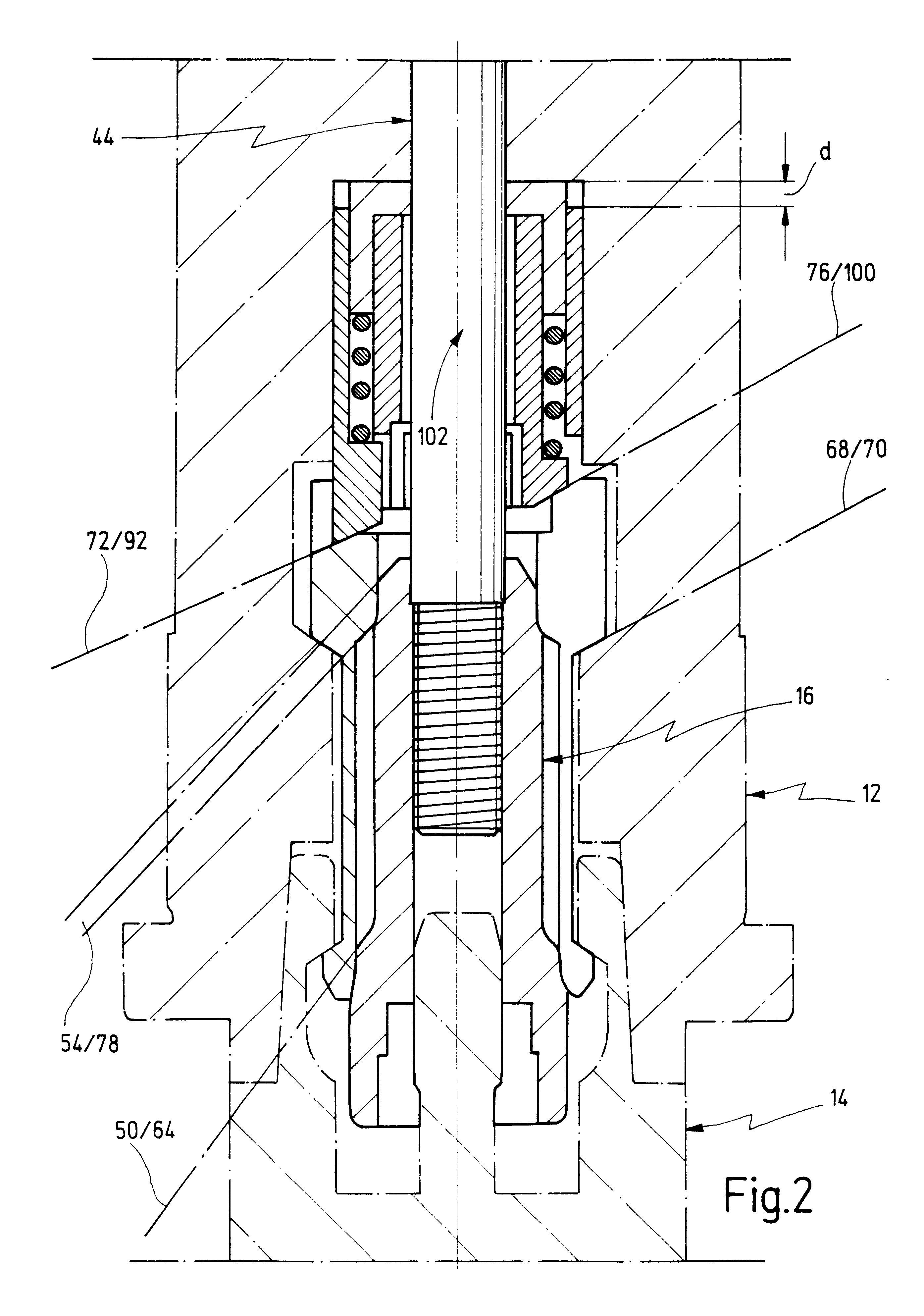
In the figures, 10 designates as a whole a spindle of a machine tool, e.g. a machining center, as it is used to accomplish program controlled drilling, milling and other types of works. Spindle 10 comprises a spindle head 12, which is directed downwards in the embodiment shown. This, however, is not to be understood in a restricting way, as also machine tools with horizontal-axed spindle are known.

In spindle head 12, a tool holder 14 is held, only the upper end of which is indicated in dash-dot in FIG. 1 and 2. A clamping jaw 16, which has on its bottom end a clamping arbor 18, serves for drawing-in and holding tool holder 14 tightly. Clamping arbor 18 has on its bottom end a first receptacle 20, in which a stud 22 of tool holder 14 engages.

In the detaching position shown in FIG. 1, in which there is not yet a firm connection between tool holder 14 and spindle head 12, there is a front end 24 of clamping arbor 18 just in contact with a bottom 26 in a second receptacle 28, which face...


PUM

PropertyMeasurementUnit
circumferenceaaaaaaaaaa
outer circumferenceaaaaaaaaaa
forceaaaaaaaaaa

Abstract

A spindle (10) is arranged in a machine tool, said spindle (10) having an axis (46), a receptacle arranged in the axis (46) and provided for receiving a shaft of a tool holder (14), and a clamping mechanism for axial fixation of the shaft in the receptacle, the clamping mechanism comprising an axially movable clamping arbor (18) with a circumference, at least one segment (60) arranged at said circumference and having at least a first and a second radial operation position, whereby said at least one segment (60) fixes said shaft positively in said receptacle, when being in the first radial operation position, first guiding means acting between the clamping arbor (18) and the at least one segment (60) such that upon axial movement of the clamping arbor (18) the at least one segment (60) is radially transferred between said first and second radial operation positions, and second guiding means arranged for holding said at least one segment (60) in the defined way when being in said second radial operation position or in any interposition between said first and said second radial operation positions.

Description

1. Field of the InventionThe invention relates to a spindle in a machine tool, with an axis, a receptacle arranged in the axis and provided for a shaft of a tool holder, and a clamping mechanism for axial fixation of the shaft in the receptacle, whereby the clamping mechanism contains an axially movable clamping arbor and at least one segment arranged on a circumference of the clamping arbor, wherein by means of a first guiding acting between the clamping arbor and the segment the at least one segment upon axially shifting of the clamping arbor is radially movable between a first and a second operation position and fixes the shaft, in the first operation position, positively in the receptacle.2. Related Prior ArtSuch a spindle with such a clamping mechanism is known, for example from "FZ" type machining centers of the applicant.In known clamping mechanisms, the tool holder is inserted, with its outer taper, in a complementary taperbored receptacle of the spindle head. A clamping arb...

Claims


Application Information

Patent Timeline
Patent Type & Authority Patents(United States)
IPC IPC(8): B23B31/02B23B31/26B23B31/117B23B19/02
CPCB23B31/265Y10T408/953Y10T82/2562Y10T409/309464Y10T82/2589
Inventor PRUST, DIRKHANINGER, RUDOLF
Owner OTT JAKOB & SPANNTECHN
Why Eureka
Try Eureka