Tool for chip removing machining and having fluid-conducting branch ducts

a technology of fluid-conducting branch ducts and tools, which is applied in the direction of turning machine accessories, manufacturing tools, shaping cutters, etc., can solve the problems of complicated and expensive manufacturing methods

Inactive Publication Date: 2003-07-22
SANDVIK INTELLECTUAL PROPERTY AB
View PDF24 Cites 98 Cited by
  • Summary
  • Abstract
  • Description
  • Claims
  • Application Information

AI Technical Summary

Benefits of technology

The present invention aims at obviating the shortcomings of previously known milling tools and at providing an improved milling tool. Therefore, a primary aim of the invention is to provide a tool which is able to lead the requisite fluid to the different cutting inserts in an effective and powerful manner so as to, in this way, optimise the cooling and / or lubricating effect of the fluid. Furthermore, the invention aims at providing a tool which may guide and make effective the flow of chips from the cutter head in such a way that erosion of the surfaces of the chip spaces is counteracted. Another aim of the invention is to create a tool, which may be manufactured in a simple and inexpensive way. Another aim of the invention is to create a tool having minimum weight, which facilitates operations at high rotational, speeds, in particular in respect to the starting and stopping of the tool.

Problems solved by technology

This manufacturing method is, however, complicated and expensive as well as giving mediocre results with regarding the ability of the fluid to cool the cutting inserts and the workpiece and to remove the liberated chips.

Method used


Image

  • Tool for chip removing machining and having fluid-conducting branch ducts
  • Tool for chip removing machining and having fluid-conducting branch ducts
  • Tool for chip removing machining and having fluid-conducting branch ducts

Examples


Embodiment Construction

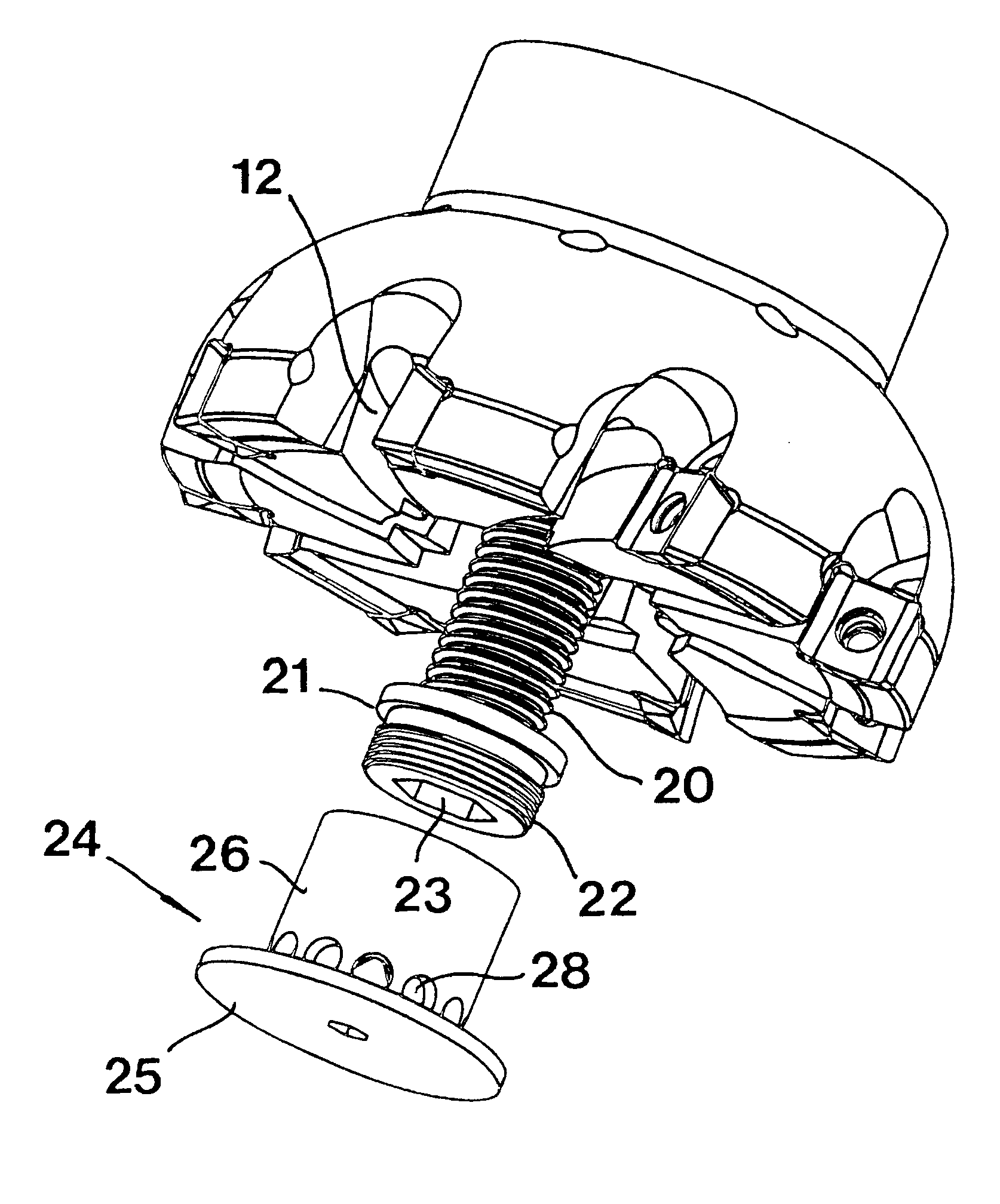
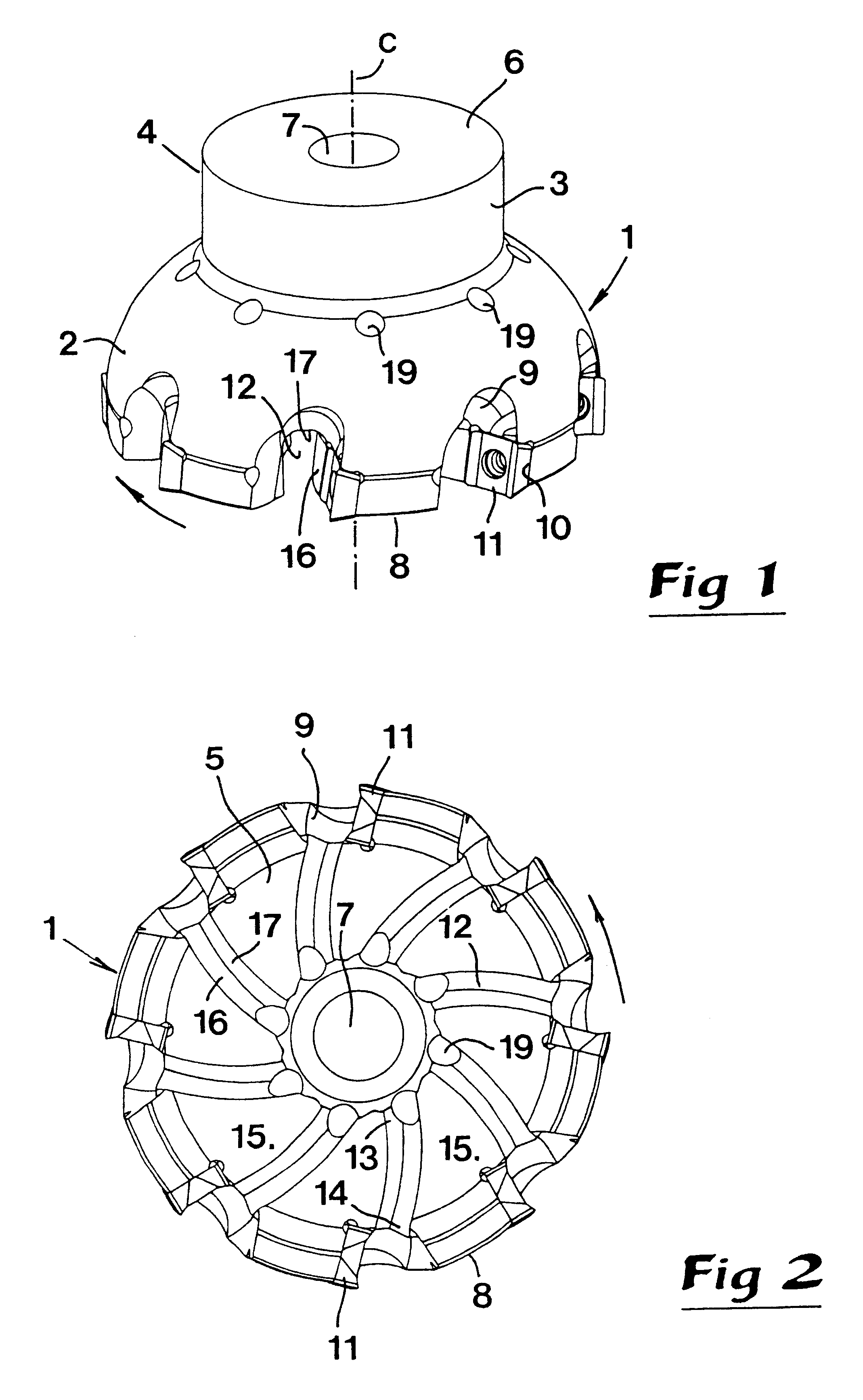
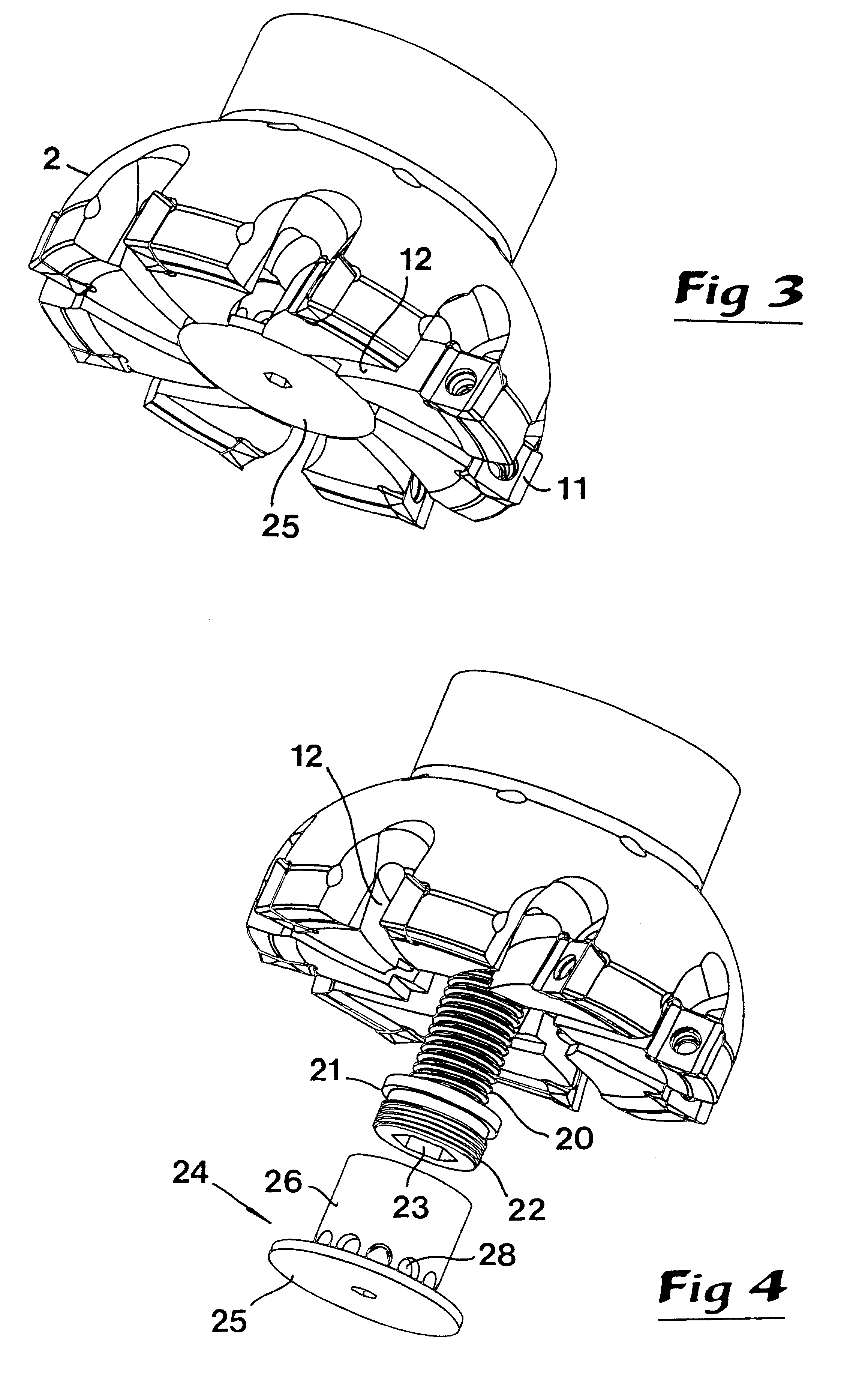
The tool illustrated in FIGS. 1 and 2 is in the form of a cutter head 1 which is rotatable around a central, geometrical axis of rotation C. A convexly spherical envelope surface 2 extends rotationally symmetrically around the axis C, which surface 2 transforms into a cylinder surface 3 on a shaft-like portion 4 of the cutter head. A first, planar end surface 5 which is opposite a second planar end surface 6 on the shaft portion 4 extends perpendicularly to the axis of rotation C. Between these end surfaces 5, 6, a central main duct 7 extends, in the form of a hole, e.g. a bore hole, through which cooling liquid or another fluid may pass. In an edge portion 8 forming a transition between the envelope surface 2 and the end surface 5, a plurality of tangentially spaced recessed chip spaces 9 are formed. In connection with said chip spaces, seats 10 are formed in which cutting inserts 11 are removably mounted. It is to advantage if said cutting inserts are of an indexable type, whereby...


PUM


Abstract

A milling tool includes a rotary cutting head having an end surface in which grooves are formed. The grooves communicate with a duct extending coaxially completely through the center of the cutting head to conduct cooling / lubricating fluid to cutting inserts mounted at outer ends of the grooves. The grooves induce a flow of fluid from inner ends of the grooves to the outer ends in response to rotation of the cutting head. A removable deflector can be attached to the end surface to deflect fluid from the main duct to the grooves.

Description

RELATED INVENTIONThis application claims priority under 35 U.S.C. .sctn..sctn. 119 and / or 365 to patent application Ser. No. 0000427-5 filed in Sweden on Feb. 11, 2000; the entire content of which is hereby incorporated by reference.This invention relates to a tool intended for chip removing machining. In particular, the tool is of the type that comprises a rotatable head having an envelope surface extending rotationally symmetrically around a central axis of geometrical rotation and an end surface extending transversely to said axis, as well as a plurality of tangentially spaced-apart cutting inserts in connection with chip spaces formed in a circumferencial edge portion in the transition between the envelope surface and the end surface. The head includes, on the one hand, an internal, central main duct which has the purpose of conducting a cooling and / or lubricating fluid received from an outside source, and, on the other hand, a number of branch ducts corresponding to the number ...

Claims


Application Information

Patent Timeline
Patent Type & Authority Patents(United States)
IPC IPC(8): B23C5/00B23C5/28B23Q11/10
CPCB23C5/006B23C5/28Y10T407/1926Y10T407/191B23C5/00
Inventor ARVIDSSON, PEDER
Owner SANDVIK INTELLECTUAL PROPERTY AB
Why Eureka
Try Eureka