Crop feed arrangement for the header of a combine harvester

a harvester and combine technology, applied in the field of headers of combine harvesters, can solve the problem of not having patents on the construction of these devices, and achieve the effect of improving the system for transferring crops from side drapers to feeder houses

Inactive Publication Date: 2005-03-15
MACDON INDS
View PDF9 Cites 90 Cited by
  • Summary
  • Abstract
  • Description
  • Claims
  • Application Information

AI Technical Summary

Benefits of technology

It is one object of the present invention to provide a header in which the system for transfer of crop from the side drapers to the feeder house is improved.

Problems solved by technology

Further commercial devices are manufactured by Deere and Company and Agco but it is believed that there are no patents disclosing the construction of these devices.

Method used


Image

  • Crop feed arrangement for the header of a combine harvester
  • Crop feed arrangement for the header of a combine harvester
  • Crop feed arrangement for the header of a combine harvester

Examples


Embodiment Construction

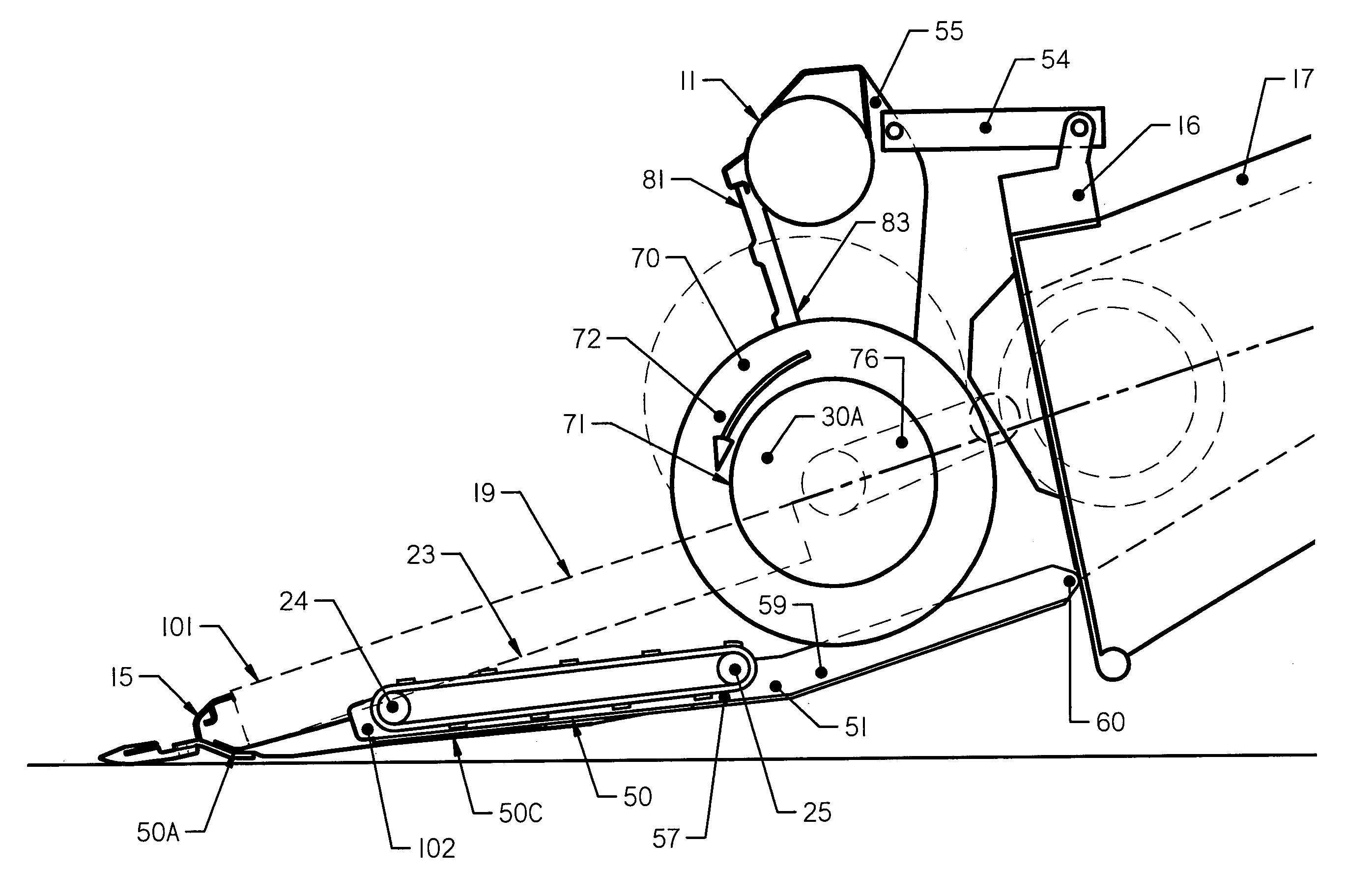
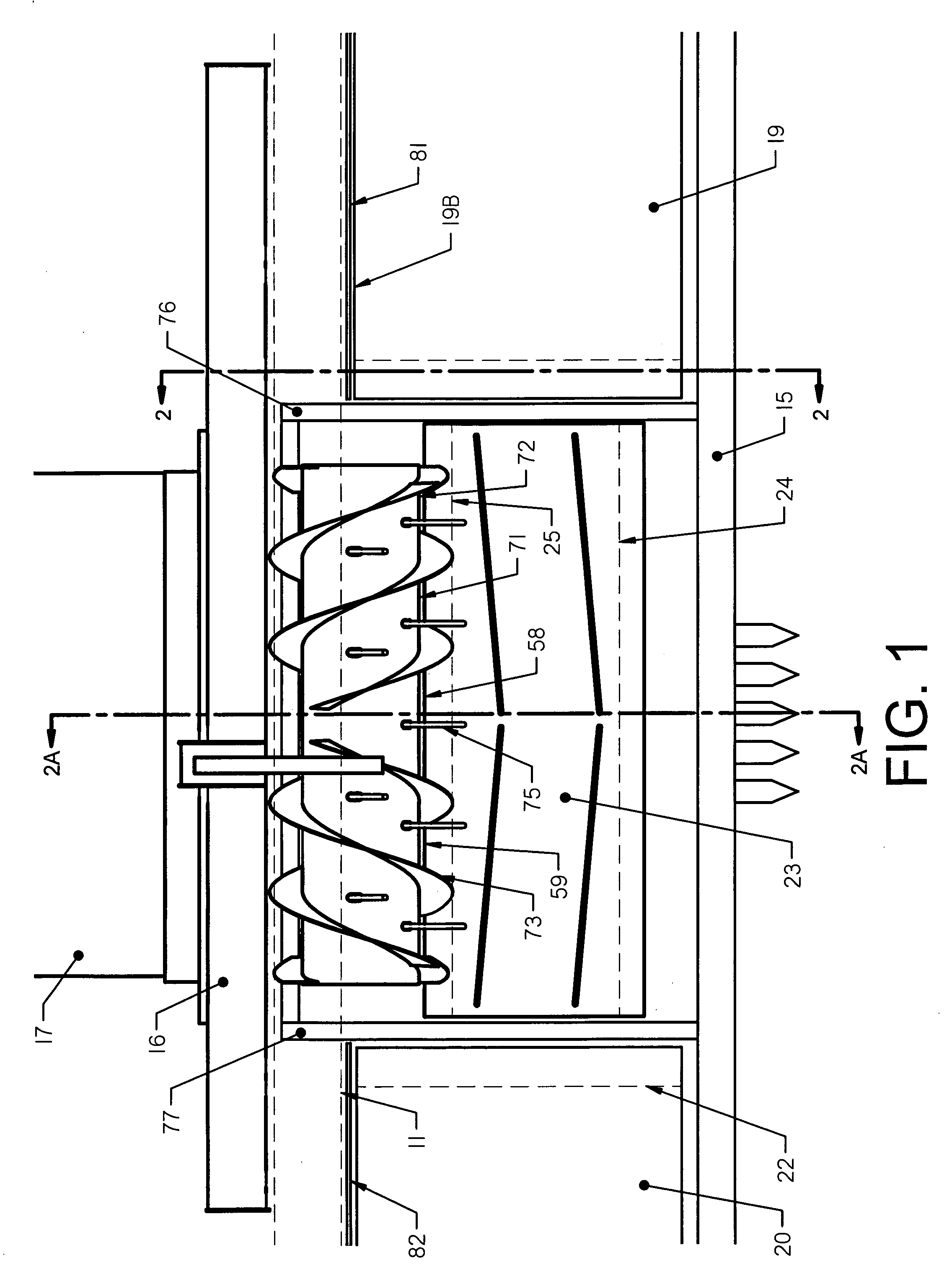
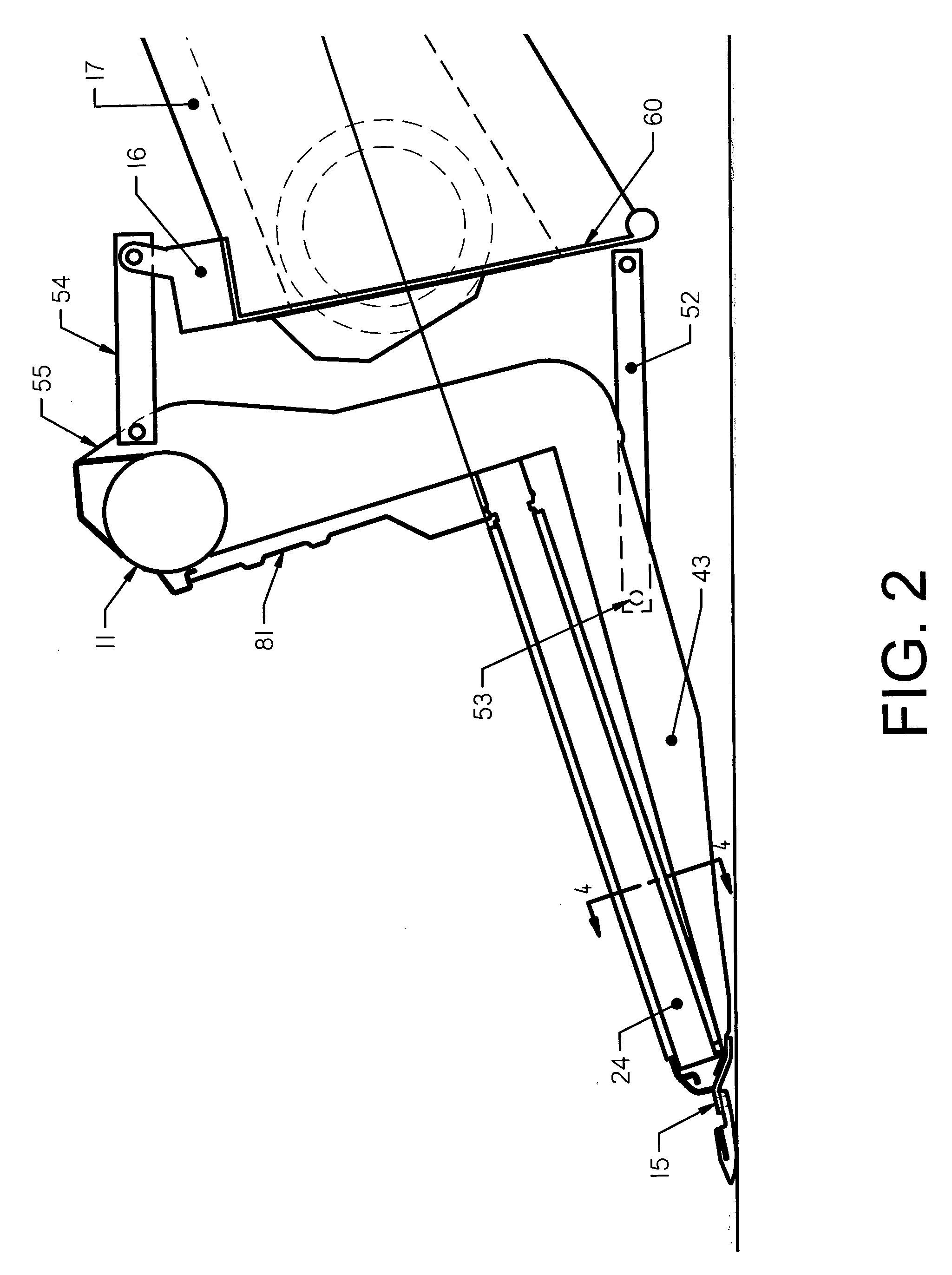
The header shown in the figures comprises a main frame 10 including a horizontal main support beam 11 extending along the length of the header along a first end 12 to a second end 13 of the header. The main frame includes forwardly extending frame members 14 at the ends of the header together with similarly arranged frame members intermediate the width of the header. At the front end of the frame members is mounted a cutter bar 15 which carries a sickle knife construction of a conventional nature. The frame 10 is attached to an adapter structure 16 attached to the feeder house 17 of a combine harvester 18.

The header includes a crop transportation system for transferring the crop from the sickle knife to the feeder house. This includes two side drapers 19 and 20 each of which includes a canvas extending from an outer guide roller 21 to an inner guide roller 22 so as to define an upper run of the canvas which carries the crop inwardly toward the center of the header. The canvas of t...


PUM


Abstract

A draper header for a combine harvester includes two side drapers each running from an outer end guide roller at a first end of the header to an inner end guide roller adjacent the discharge location of the header and a central feed draper located at the discharge location and including a front guide roller just behind the cutter bar and running to a rear guide roller in front of the feeder house of the combine harvester. An auger is located between the discharge rollers with a front edge of the flight forward of the rear end of the discharge rollers to feed the material inwardly and underneath the auger to the inlet of the feeder house. A pan is located underneath the auger and is mounted on a common structure with the feed draper for common pivotal movement about a transverse horizontal axis.

Description

This invention relates to a crop feed arrangement for the header of a combine harvester. BACKGROUND OF THE INVENTION A header for a crop harvesting machine generally comprises a main longitudinal support member in the form of an elongate tube which extends across substantially the full width of the header frame and defines a main structural member for the header frame. The tube carries a plurality of forwardly and downwardly extending support beams which include a first portion extending downwardly and a second portion attached to a lower end of the first portion and extending forwardly therefrom toward a forward end of the support beams. The cutter bar is attached to the forward end of the support beams and is thus held thereby in a position generally parallel to the main support tube. In U.S. Pat. No. 4,956,966 issued September 1990 and U.S. Pat. No. 5,005,343 issued April 1991 by Patterson and assigned to the present Assignee is disclosed a header which utilizes two side drapers ...

Claims


Application Information

Patent Timeline
Patent Type & Authority Patents(United States)
IPC IPC(8): A01D41/00A01D41/14A01D57/00A01D57/20
CPCA01D57/20A01D41/14
Inventor PATTERSON, ROGER L.KIDD, BRUCE ROBERT
Owner MACDON INDS
Why Eureka
Try Eureka