Speed reducer and electric retractable rearview mirror equipped with the speed reducer

Inactive Publication Date: 2005-03-29
MURAKAMI CORP
View PDF18 Cites 19 Cited by
  • Summary
  • Abstract
  • Description
  • Claims
  • Application Information

AI Technical Summary

Benefits of technology

is to provide the speed reducer capable of always steadily and smoothly transmitting the driving force regardless of the err caused by incorrectly combining frames to form a gear box. Furthe

Problems solved by technology

Accordingly, the driving force can not be steadily and smoothly transmitted.
Consequently, a problem had been arisen such that a noise is made or a gear is abnormally worn away.
However, when two frames are combined together to form aforementioned speed reducer, there was a limit to improve the accuracy for engaging two gears with each

Method used


Image

  • Speed reducer and electric retractable rearview mirror equipped with the speed reducer
  • Speed reducer and electric retractable rearview mirror equipped with the speed reducer
  • Speed reducer and electric retractable rearview mirror equipped with the speed reducer

Examples


Embodiment Construction

Now the preferred embodiment of a speed reducer and an electric retractable rear view mirror equipped with a speed reducer with regard to the present invention is explained in detail. Hereinafter, the speed reducer is explained as one example when said speed reducer is applied to the electric retractable rearview mirror. However, an application of said speed reducer is not restricted to said electric retractable rearview mirror.

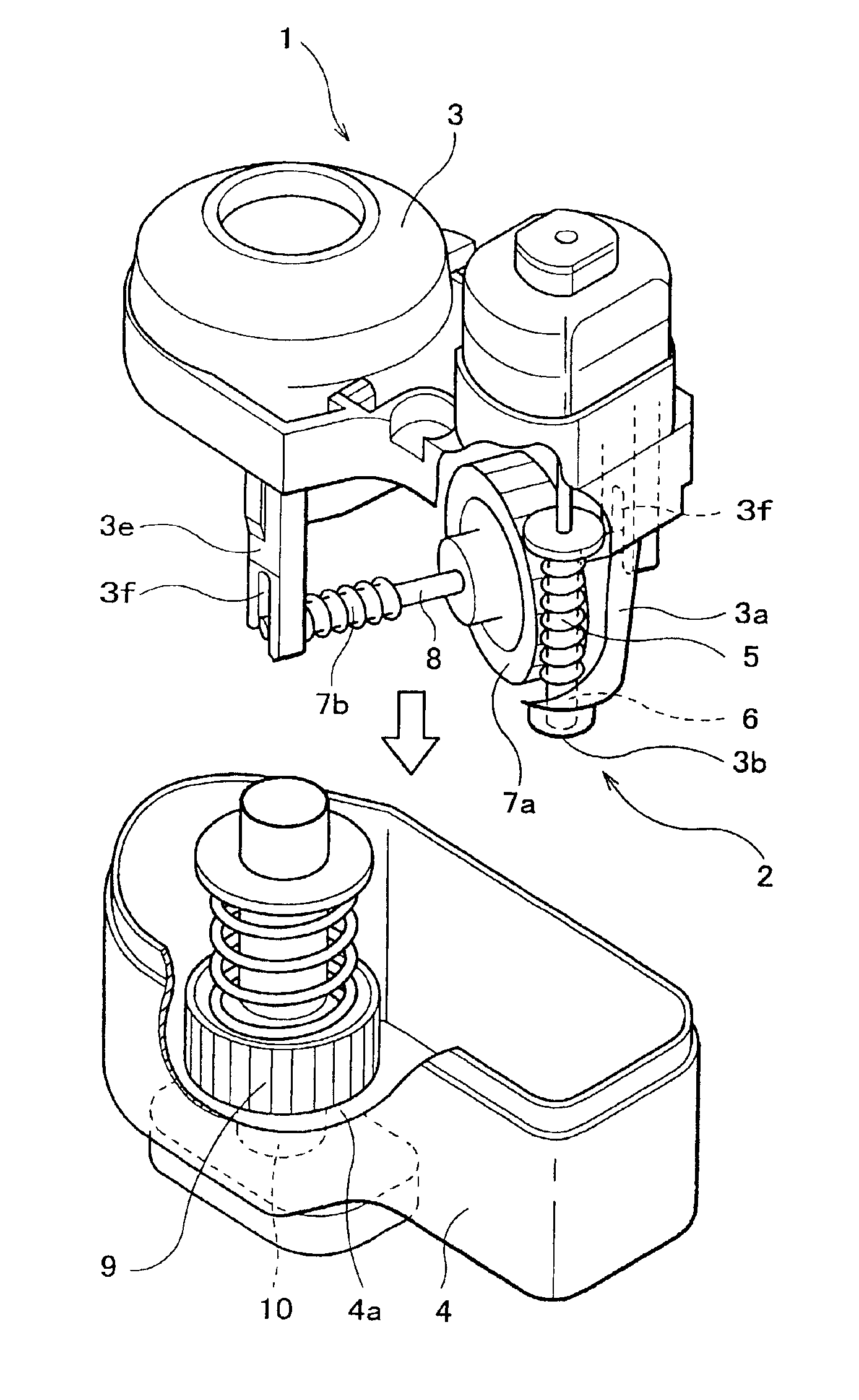
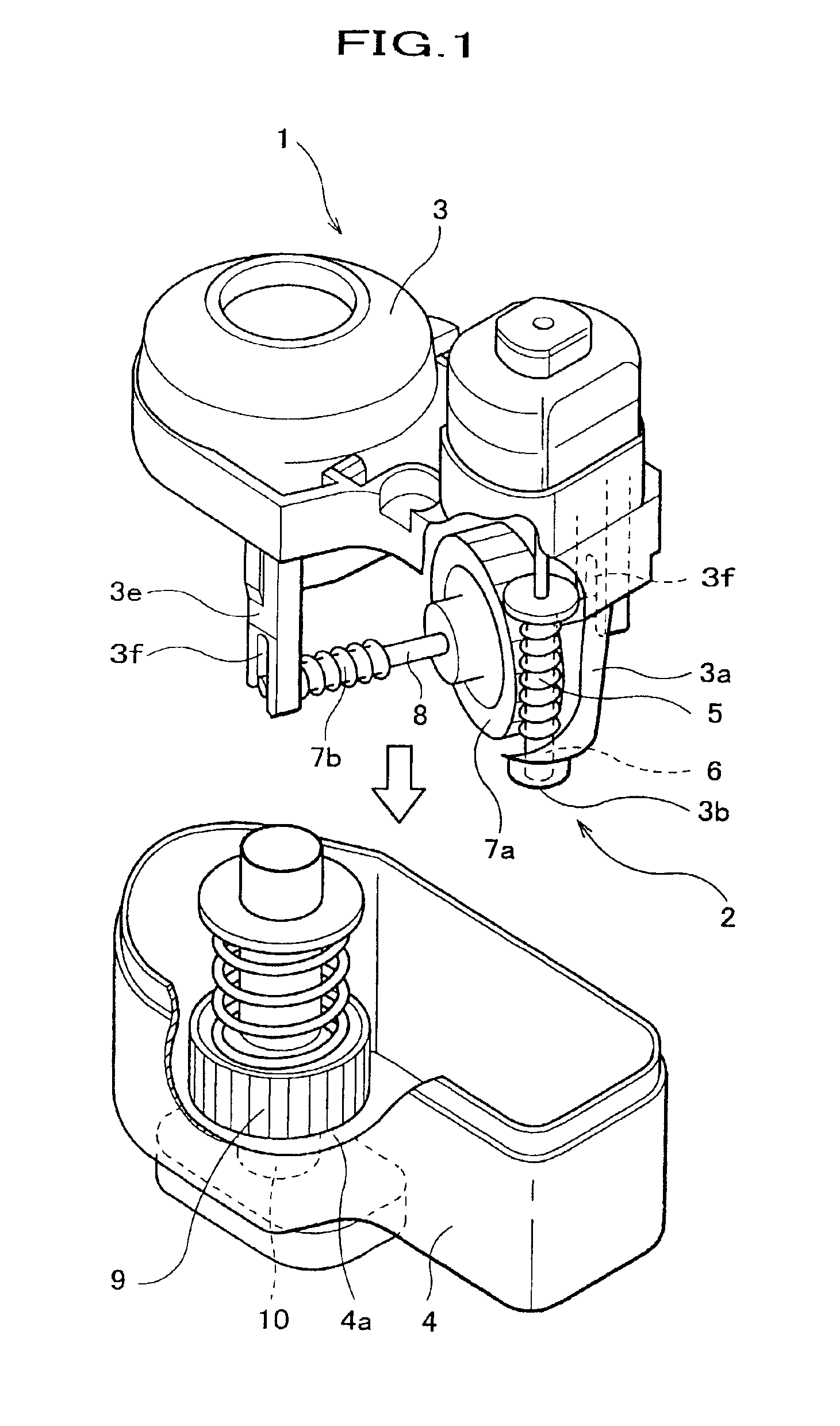
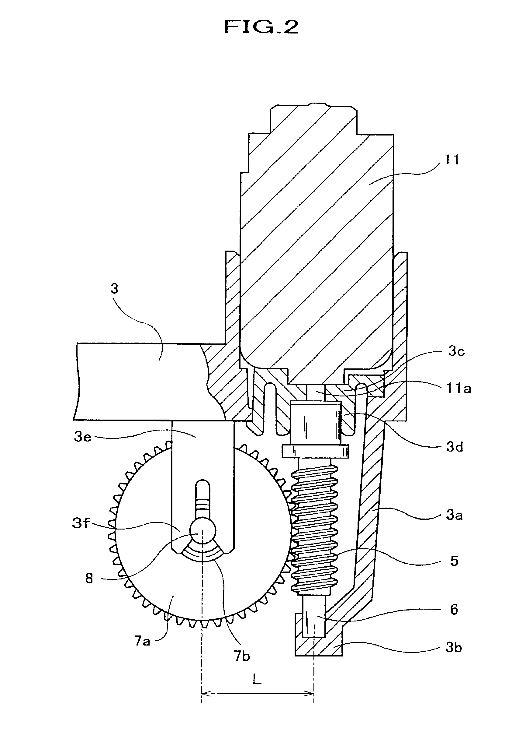
FIG. 1 is a perspective view of the speed reducer with regard to the present invention. FIG. 2 is an enlarged cross sectional view of a main part of the first frame of the speed reducer shown in FIG. 1. A speed reducer 1 comprises a gearbox 2 having a first frame 3 and a second frame 4 combined together, wherein an input gear 5, intermediate gears 7a, 7b, and an output gear 9 are provided.

An input shaft 6 having the input gear 5 fixed thereon and the intermediate shaft 8 having intermediate gears 7a, 7b fixed thereon are rotatably supported by the first frame...


PUM


Abstract

A speed reducer including a gear box having a first frame and a second frame combined together, an input gear fixed on an input shaft being rotated by a driving force, an output gear fixed on an output shaft, an intermediate shaft, intermediate gears fixed on the intermediate shaft to reduce a speed of rotation of the input gear for being transmitted to said output gear, wherein the input shaft and the intermediate shaft are rotatably supported by the first frame for always maintaining the length between each core of the input shaft and the intermediate shaft as a predetermined length.

Description

BACKGROUND OF THE INVENTION1. Field of the InventionThe present invention relates to a speed reducer capable of steadily and smoothly transmitting a driving force from an input shaft to an output shaft after the driving force is provided on the input shaft.The present invention also relates to an electric retractable rearview mirror equipped with the speed reducer for using in an automobile.2. Prior ArtConventionally, an electric retractable rearview mirror is mounted on an automobile and the like such that a driving force provided by a motor can cause a mirror body to be retracted and be returned to an original position for usage.Above-mentioned rearview mirror is retracted and returned to an original position as a following way. As shown in FIG. 3, a motor 11 is mounted on inside the mirror body. The driving force provided by the motor 11 is transmitted to a shaft 10 (an output shaft) fixed on a base member 22 attached to a vehicle body. Then, the mirror body turns on the shaft 10...

Claims


Application Information

Patent Timeline
IPC IPC(8): B60R1/074B60R1/062F16H1/16F16H57/028F16H57/037F16H57/038F16H57/039
CPCB60R1/074Y10T74/19828
Inventor YAMAUCHI, KAZUNARIMORIOKA, TAKESHI
Owner MURAKAMI CORP
Why Eureka
Try Eureka