Rotary joint for joining two waveguides

a waveguide and rotary joint technology, applied in waveguide devices, basic electric elements, electrical apparatus, etc., can solve the problems of normal increase in losses, increase in losses, and increase in losses, so as to reduce losses and phase errors, good electrical connection, and good shielding

Inactive Publication Date: 2012-09-27
SONY CORP
View PDF4 Cites 22 Cited by
  • Summary
  • Abstract
  • Description
  • Claims
  • Application Information

AI Technical Summary

Benefits of technology

[0012]The present invention is based on the idea to provide a rotary joint in which the portions contact each other for electrical connection in a jointed state such that a good electrical connection is provided, especially for higher frequencies. Thus, losses and phase errors are reduced. Also, a good shielding from undesired electromagnetic waves in the environment of the rotary joint is provided. The rotary joint can switch to a non-jointed state, in particular in which there is less, preferably no, contact pressure and / or abrasion, compared to the jointed state, between the portions, in particular between the contact surfaces for electrical connection (electrical contact surfaces). All this reduces mechanical stress and abrasion and ensures proper operation over a long life time. Since there is less abrasion, the transmission of the electromagnetic waves is more predictable, as the unknown variable caused by abrasion over time is reduced or eliminated. For example an antenna measurement, especially the measurement of the co-polar component and cross-polar component, can thus be more predictable and / or precise. Further, a relatively compact design of the rotary joint can be provided. Also, no transition from rectangular waveguide to circular waveguide is necessary and no mode converters for circular waveguide modes or mode filters are necessary, which reduces the losses. The direction of the vector of the electric field of the electromagnetic wave (polarization) in the fundamental mode can be rotated in an easy manner. In particular, when the rotary joint is used as a polarizer, exactly the same amplitude and phase response can be expected for the two different angular positions or polarizations due to geometrical symmetry. Furthermore a high bandwidth over the entire waveguide band can be provided.

Problems solved by technology

This induces some undesired amplitude and / or phase errors.
For higher frequencies the losses normally become undesirably high.
Thus, the losses are relatively high and the mechanical dimensions are very bulky.

Method used


Image

  • Rotary joint for joining two waveguides
  • Rotary joint for joining two waveguides
  • Rotary joint for joining two waveguides

Examples


first embodiment

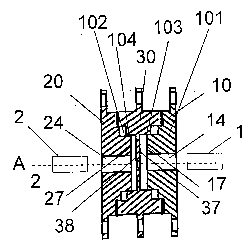
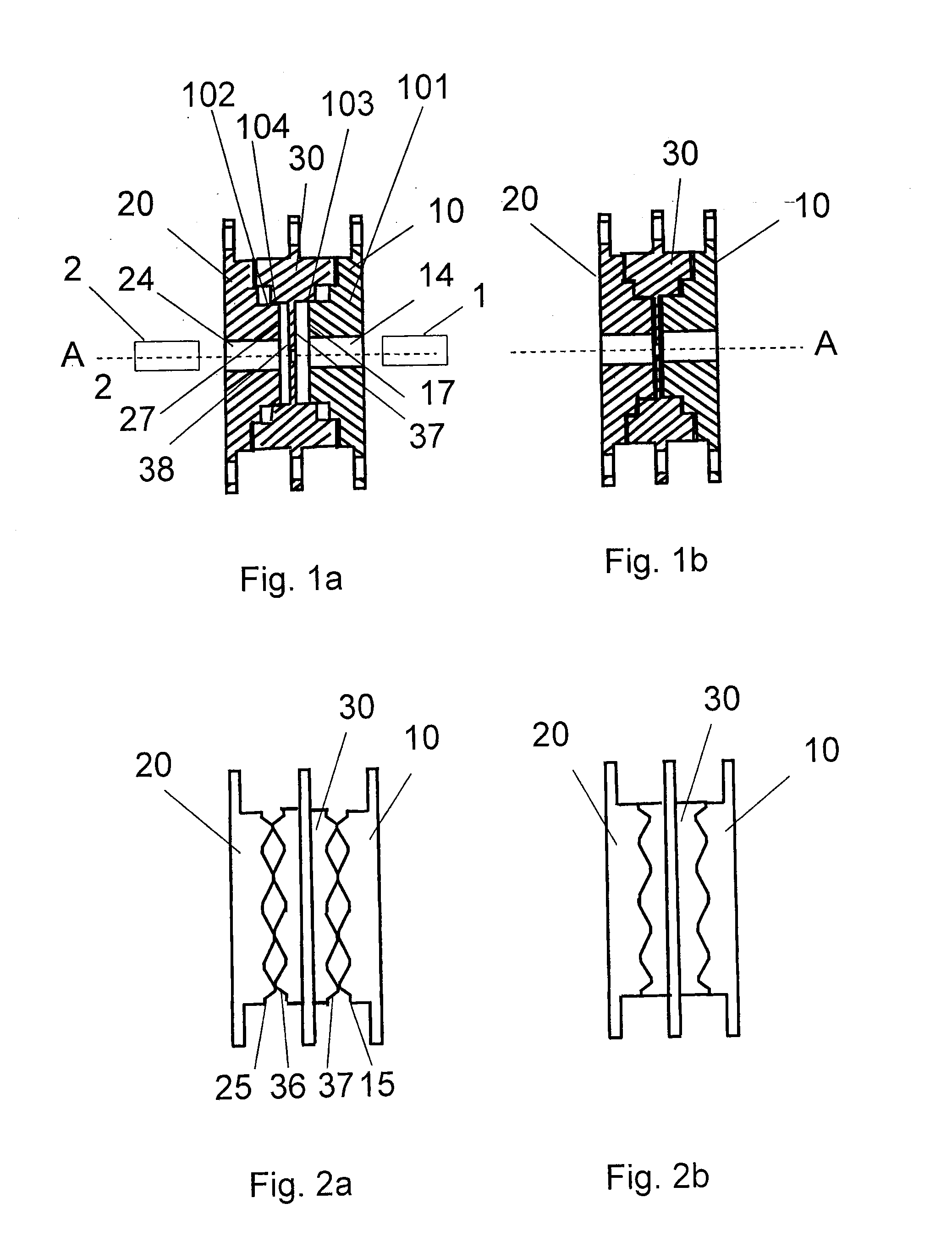
[0028]FIG. 1a shows a sectional side view of a rotary joint in a non-jointed state and FIG. 1b shows the same rotary joint in a jointed state. The rotary joint comprises a first portion 10 adapted to receive a first hollow rectangular waveguide 1, a second portion 20 adapted to receive a second hollow rectangular waveguide 2, and a third portion 30 adapted for polarization rotation and arranged between the first portion 10 and the second portion 20. The first portion 10, the second portion 20 and the third portion 30 are each a slab. This means that their radial dimensions are much larger than their width. In particular, the portions 10, 20, 30 are each a round slab. Each of the portions 10, 20, 30 can be made of a single part or of multiple parts.

[0029]In FIG. 1a and FIG. 1b, the first portion 10 comprises a first opening 14 adapted to receive the first rectangular waveguide 1, and the second portion 20 comprises a second opening 24 adapted to receive the second rectangular wavegu...

second embodiment

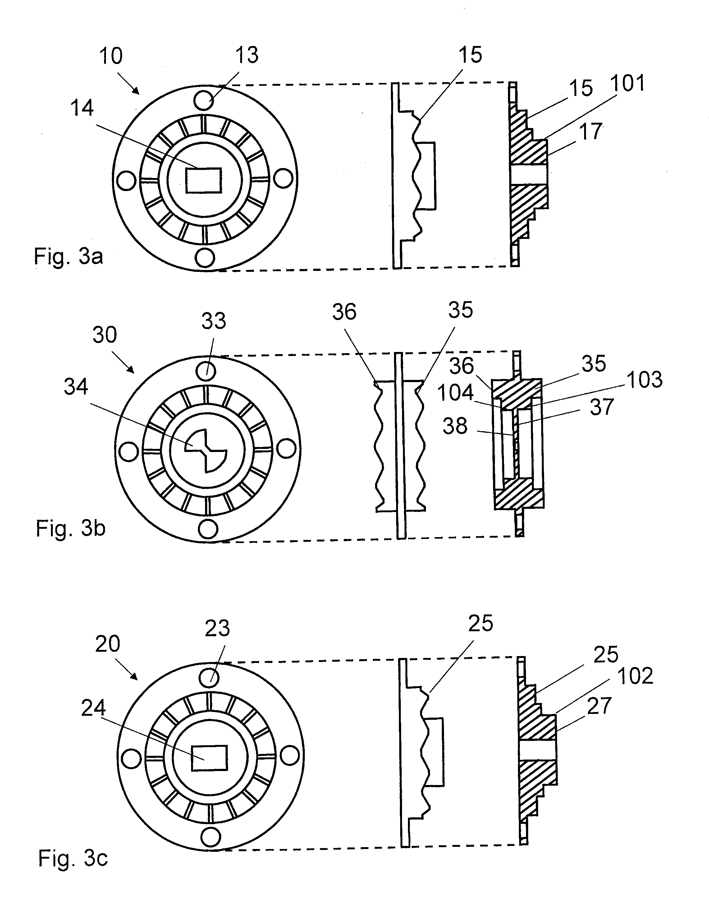
[0044]The rotary joint further comprises a third adapter 31 and a third rotatable adapter part 32. The third rotatable adapter part 32 is rotatable attached to the third adapter 31. The third portion 30 is attachable to the third rotatable adapter part 32. The third portion 30 shown in FIG. 3b is attachable to the third rotatable adapter part 32 in FIG. 4 by means of fasteners through holes 33 provided in the third portion 30 and corresponding holes 39 provided in the third rotatable adapter part 32. The third adapter 31 is movable in the direction of the central axis A, as indicated in FIG. 4. In general, there can be more than two movable adapters and rotatable adapter parts, as pointed out in the second embodiment with reference to FIG. 7a and FIG. 7b.

[0045]The rotary joint further comprises an actuator adapted to rotate the second portion 20 and the third portion 30. In the embodiment of FIG. 4 an actuator in form of a motor can be provided in or near each of the second adapter...


PUM


Abstract

The present invention relates to a rotary joint for joining two waveguides for guiding electromagnetic waves, comprising a first portion adapted to receive a first waveguide, a second portion adapted to receive a second waveguide, and a third portion adapted for polarization rotation and arranged between the first portion and the second portion. The rotary joint is configured such that two portions selected from the group comprising the first portion, the second portion and the third portion are rotatable between at least two different angular positions around a central axis. Further, the rotary joint being configured to switch between a jointed state, in which the portions contact each other for electrical connection, and a non-jointed state. The present invention also relates to a method of operating such a rotary joint and a computer program and a computer readable non-transitory medium for implementing such a method.

Description

CROSS-REFERENCE TO RELATED APPLICATIONS[0001]The present application claims priority of European patent application 11 159 229.1 filed on Mar. 22, 2011.FIELD OF THE INVENTION[0002]The present invention relates to a rotary joint for joining two waveguides for guiding electromagnetic waves, in particular two hollow rectangular waveguides. The present invention also relates to a method of operating such a rotary joint and a computer program and a computer readable non-transitory medium for implementing such a method.BACKGROUND OF THE INVENTION[0003]In antenna measurements, particularly in near-field measurements, the acquisition of two orthogonal field components is essential. Normally, this is done by rotating a field-probe by 90° around its central axis, typically an open ended waveguide or horn antenna. The first polarization of an antenna under test is measured by the probe in the first orientation of the antenna under test, and the orthogonal polarization can be acquired in the se...

Claims


Application Information

Patent Timeline
Patent Type & Authority Applications(United States)
IPC IPC(8): H01P1/06
CPCH01P1/165H01P1/065
Inventor BLECH, MARCEL DANIELKOCH, STEFAN
Owner SONY CORP
Why Eureka
Try Eureka