
Cable

a technology of stranded wires and cables, applied in the field of cables, can solve the problems of difficulty in satisfying both high bending durability and high flexibility, and none of the related arts discloses a cable for achieving both high bending durability and high flexibility, and achieve the effect of reducing the physical mutual contact of the stranded wires and significantly reducing the abrasion or disconnection caused by bending

Inactive Publication Date: 2011-01-13
HITACHI CABLE
View PDF5 Cites 19 Cited by
  • Summary
  • Abstract
  • Description
  • Claims
  • Application Information

AI Technical Summary

Benefits of technology

[0010]Therefore, it is an object of the invention to provide a cable that has both high bending durability and high flexibility by reducing contact between stranded wires so as to prevent the cable from abrasion or disconnection caused by bending.
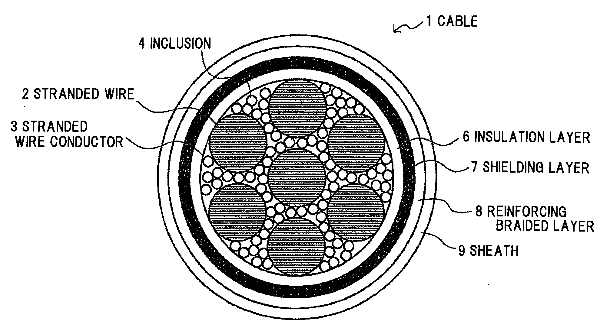
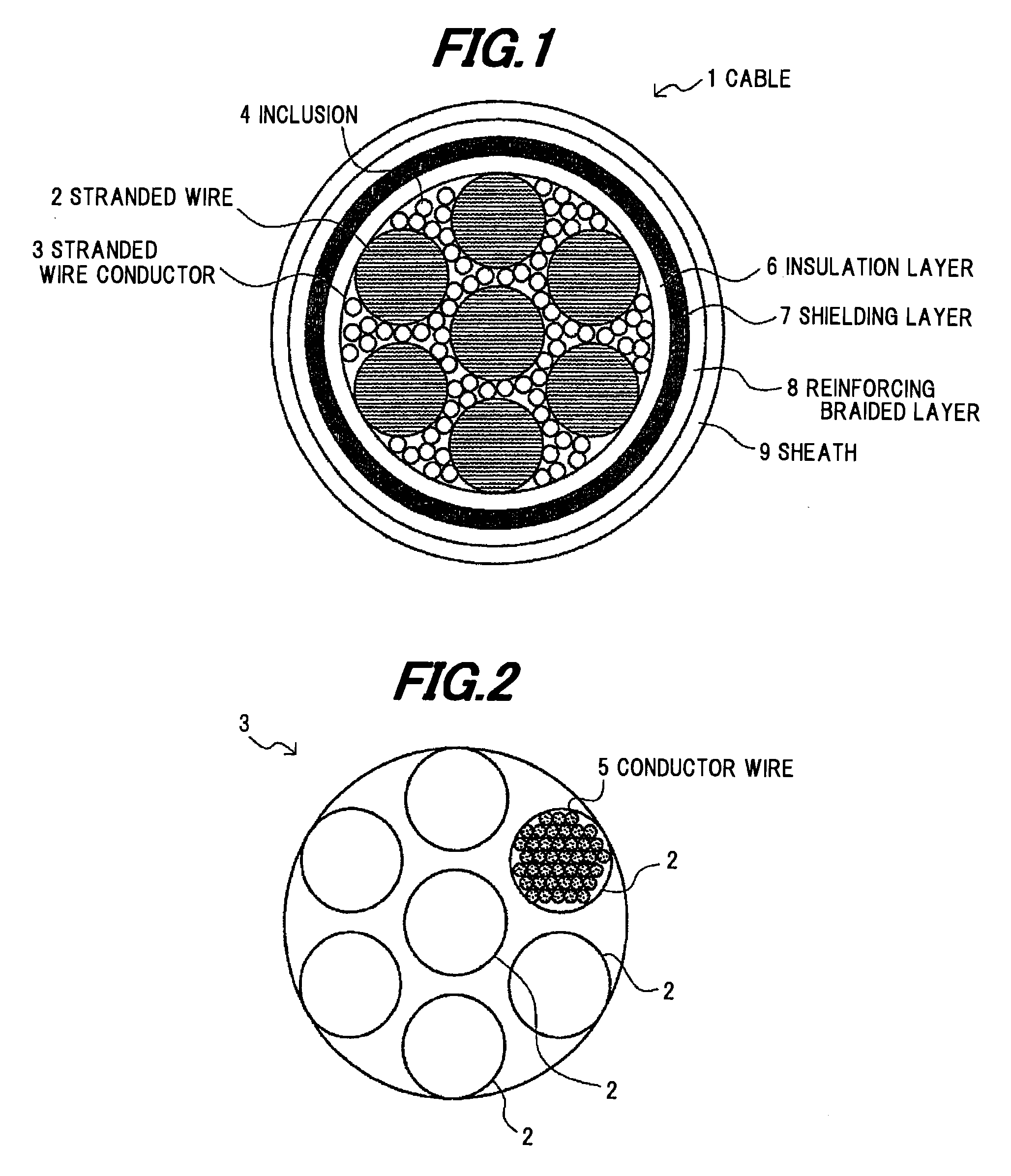
[0025]According to one embodiment of the invention, a cable is constructed such that inclusions are located at least at a clearance of the shortest distance between two adjacent stranded wires (child stranded wires) in a stranded wire conductor of the cable, so that the physical mutual contact of the stranded wires can be reduced. Due to the reduction in physical mutual contact of the stranded wires, the abrasion or disconnection caused by bending can be significantly reduced in comparison with the conventional cable.

Problems solved by technology

However, it has been difficult to satisfy both high bending durability and high flexibility.
However, none of the related arts discloses a cable for achieving both high bending durability and high flexibility.

Method used


Image

  • Cable
  • Cable
  • Cable

Examples


example

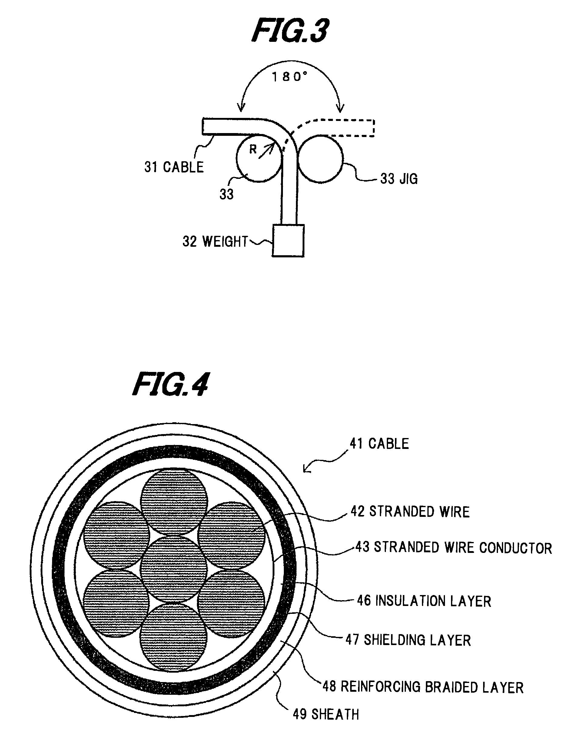
[0047]The cable 1 of Example having a cable structure shown in FIG. 1 and the cable 41 of Comparative Example having a cable structure shown in FIG. 4 were fabricated.

[0048]Example and Comparative Example have almost the same cable structure except that Example has the inclusions 4 and Comparative Example does not have the inclusions 4.

[0049]The stranded wires (child stranded wires) 2 were formed by twisting tin-plated annealed copper wires of 0.08 mm in diameter as the conductor wires 5. Further, an external diameter of the stranded wire 2 is 1.0 mm.

[0050]The stranded wire conductor 3 was formed by further twisting the stranded wires (child stranded wires) 2 formed by twisting the conductor wires 5 so as to allow at least one of the inclusions 4 to be located at least at a clearance of the shortest distance between the respective stranded wires 2 in order to prevent the contact of the stranded wires 2.

[0051]As the inclusions 4, a yarn twisted member formed by twisting fibrous yarns...


PUM


Abstract

A cable includes an inclusion containing stranded wire conductor that includes a plurality of stranded wires formed by twisting a plurality of conductor wires, and a plurality of thin diameter inclusions having an external diameter thinner than that of each of the stranded wires. The inclusion containing stranded wire conductor is formed by together twisting a plurality of the stranded wires and a plurality of the thin diameter inclusions so as to allow one of the thin diameter inclusions to be located between adjacent stranded wires of a plurality of the stranded wires.

Description

[0001]The present application is based on Japanese patent application No. 2009-162100 filed Jul. 8, 2009, the entire contents of which are incorporated herein by reference.BACKGROUND OF THE INVENTION[0002]1. Field of the Invention[0003]This invention relates to a cable and, in particular, to a cable used for an environment where bending is repeatedly applied, such as robots and automobiles.[0004]2. Description of the Related Art[0005]For example, a cable for automobiles used in the environment where bending is repeatedly applied, such as an unsprung portion (a portion under a suspension device) of the automobiles where bending is repeated according to movement of wheels is needed to have not only high bending durability, but also, for example, high flexibility in terms of ease of routing work. However, it has been difficult to satisfy both high bending durability and high flexibility.[0006]FIG. 4 is a cross-sectional view schematically showing a conventional cable.[0007]The cable 41...

Claims


Application Information

Patent Timeline
IPC IPC(8): H01B7/18H01B7/02
CPCH01B7/0009H01B7/1895H01B7/04
Inventor ESHIMA, HIROTAKA
Owner HITACHI CABLE
Learn More