Unlock instant, AI-driven research and patent intelligence for your innovation.

Method of transmitting data on multiple carriers from a transmitter to a receiver and receiver designed to implement the said method

Inactive Publication Date: 2005-04-05
MITSUBISHI ELECTRIC CORP
View PDF8 Cites 30 Cited by
  • Summary
  • Abstract
  • Description
  • Claims
  • Application Information

AI Technical Summary

Benefits of technology

The aim of the present invention is therefore to propose a method which makes it possible to correct the sampling frequency shift and which facilitates, the implementation of the synchronization of the receiver of an OFDM system, or which can even make it possible to dispense with the slaving of the sampling frequency.

Problems solved by technology

However, the shift of the receiver sampling frequency feR with respect to the transmitter sampling frequency feE has three main consequences on the demodulation process:a loss of orthogonality between the base functions of the received signal and the base functions used for demodulation, resulting in interference between the signals modulating the different sub-carriers of the same OFDM symbol (the distortion introduced then is generally very low and can be considered to be negligible, which is done by the invention),a slipping of the analysis window which results in interference between consecutive OFDM symbols when this slippage is greater than an acceptable range, anda phase shift between the demodulated signals of two consecutive symbols, a phase shift varying from carrier to carrier and directly related to the variation in the position of the analysis window.
However, this solution proves to be relatively cumbersome to implement as a result in particular of the use of a voltage controlled crystal oscillator (VCXO) which is also expensive.

Method used


Image

  • Method of transmitting data on multiple carriers from a transmitter to a receiver and receiver designed to implement the said method
  • Method of transmitting data on multiple carriers from a transmitter to a receiver and receiver designed to implement the said method
  • Method of transmitting data on multiple carriers from a transmitter to a receiver and receiver designed to implement the said method

Examples


Embodiment Construction

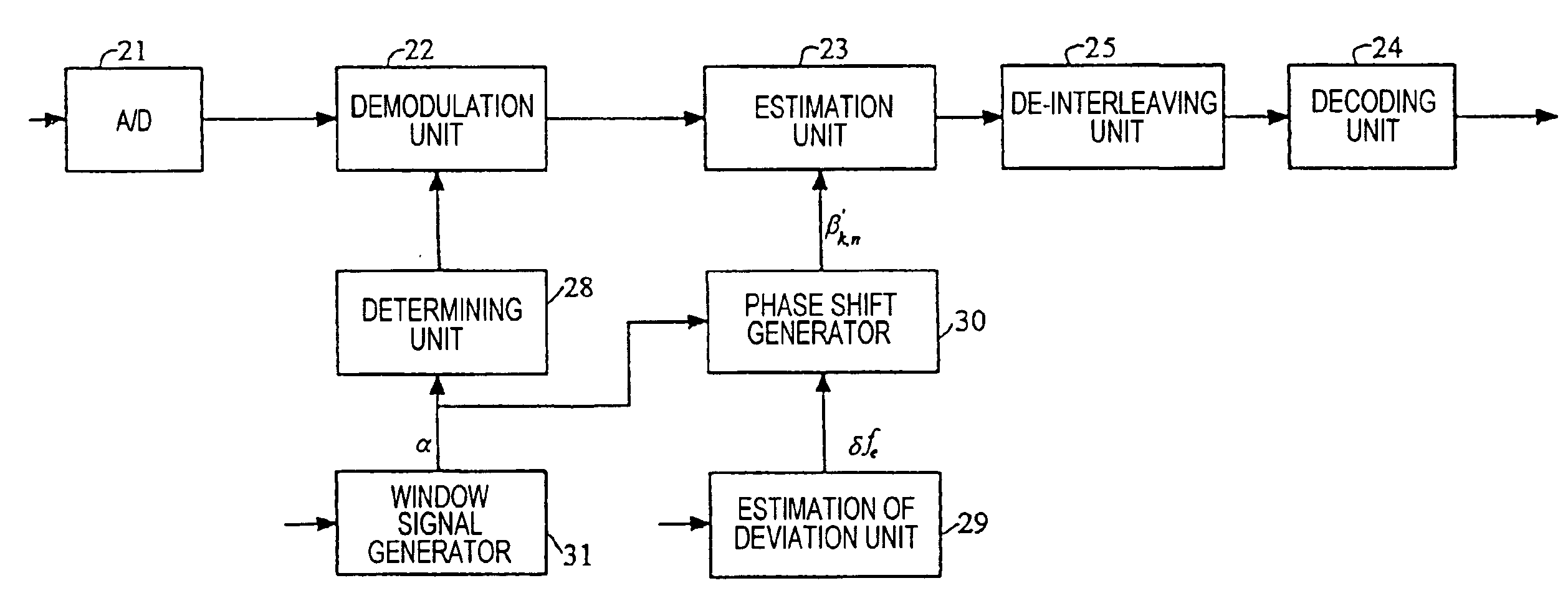
The receiver 20 depicted in FIG. 3 has, like the one depicted in FIG. 1, an analogue to digital conversion unit 21, a demodulation unit 22, for example in the form of a Fourier transform calculation unit, an estimation unit 23, a de-interleaving unit 25 and decoding unit 24.

The demodulation unit 22 and estimation unit 23 are synchronized by means of a time base which delivers a signal to them at a sampling frequency feR, referred to as the receiver sampling frequency.

The receiver 20 also has a unit 28 provided for determining, from a clock signal delivered by a time base (not shown) and at a frequency which is related to the receiver sampling frequency feR, an analysis window F for the signal delivered by the unit 21. This analysis window F is delivered to the demodulation unit 22 so as to form a block of samples to which the demodulation is applied.

According to the present invention, the estimation unit 23 carries out the demodulation of the received signal by correcting, not only ...


PUM


Abstract

A method of transmitting data on multiple carriers is disclosed, the method consisting, on a transmitter side, of binary to signal coding of the data to be transmitted so as to form modulation signals, of modulating a plurality of sub-carriers with the modulation signals as to form symbols, referred to as OFDM symbols, and then of transmitting, over a channel between the transmitter and a receiver, the OFDM symbols at a rate which is related to a sampling frequency referred to as the transmitter sampling frequency, and, on the receiver side, of determining, from a clock signal at a frequency related to a sampling frequency referred to as the receiver sampling frequency, an analysis window for the signal received from the transmitter so as to form a block of samples, and of estimating the transmitted modulation signals by demodulating the sub-carriers for the block of samples under consideration.

Description

FIELD OF THE INVENTIONThe present invention concerns a method of transmitting data on multiple carriers from a transmitter to a receiver of a data transmission system using multiple carrier modulation, also referred to as OFDM (Orthogonal Frequency Division Multiplex). It also concerns a receiver which is particularly intended to implement the said data transmission method.BACKGROUND OF THE INVENTIONThe technique of modulation on multiple carriers, referred to as OFDM, is known and consists of distributing the data to be transmitted over a large number of sub-carriers, which makes it possible to obtain a symbol time appreciably longer than the spread of the pulse response of the transmission channel between a transmitter and a receiver of the said transmission system. This technique is perfectly adapted to radio transmissions, with fixed, mobile or portable reception.A description of a transmission system of the OFDM (Orthogonal Frequency Division Multiplex) type can be found in an ...

Claims


Application Information

Patent Timeline
IPC IPC(8): H04L27/26H04L25/02H04L7/00H04J11/00
CPCH04L25/022H04L25/0232H04L27/2679H04L27/2657H04L27/2662
Inventor CASTELAIN, DAMIEN
Owner MITSUBISHI ELECTRIC CORP