Method and apparatus for relayed communication using band-pass signals for self-interference cancellation

a bandpass signal and self-interference cancellation technology, applied in the field of radio frequency or optical communication system, can solve the problems of inability to fully realize the advantages of self-interference cancellation, inconvenient retrofitting of large number of existing systems, and high cost of retrofitting

Inactive Publication Date: 2005-06-14
VIASAT INC
View PDF38 Cites 61 Cited by
  • Summary
  • Abstract
  • Description
  • Claims
  • Application Information

AI Technical Summary

Benefits of technology

[0011]Self-interference cancellation is provided in two-way relayed electromagnetic communication between a first device and a second device through a relay station wherein a representation of a relayed composite signal above baseband and a representation of a locally modulated interface signal above baseband interact to effect the self-interference cancellation. Specifically, the composite signal, which contains a relayed version of the locally modulated (near) signal from the first device and a relayed version of a modulated far signal from the second device, is received at the first device from the relay station. The composite signal is...

Problems solved by technology

However, these techniques have focused on structures which make it expensive and inconvenient to retrofit the large number of existing systems for the capability of self-interference cancellation.
In addition, these techniques have failed to take into account various distortions introduced into the transmit signal.
As a result, advantages of self-interference cancellation have not been fully realized.
Retrofitting a facility such as an existing satellite communication facility for self-interference cancellation capability has been expensive and inconvenient because current techniques of self-interference cancellation have all focused on structures that require the construction of completely new systems or require tapping into existing systems at inconvenient and/or difficult-to-access locations.
Self-interference cancellation techniques that tap at the output of the modu...

Method used


Image

  • Method and apparatus for relayed communication using band-pass signals for self-interference cancellation
  • Method and apparatus for relayed communication using band-pass signals for self-interference cancellation
  • Method and apparatus for relayed communication using band-pass signals for self-interference cancellation

Examples


Embodiment Construction

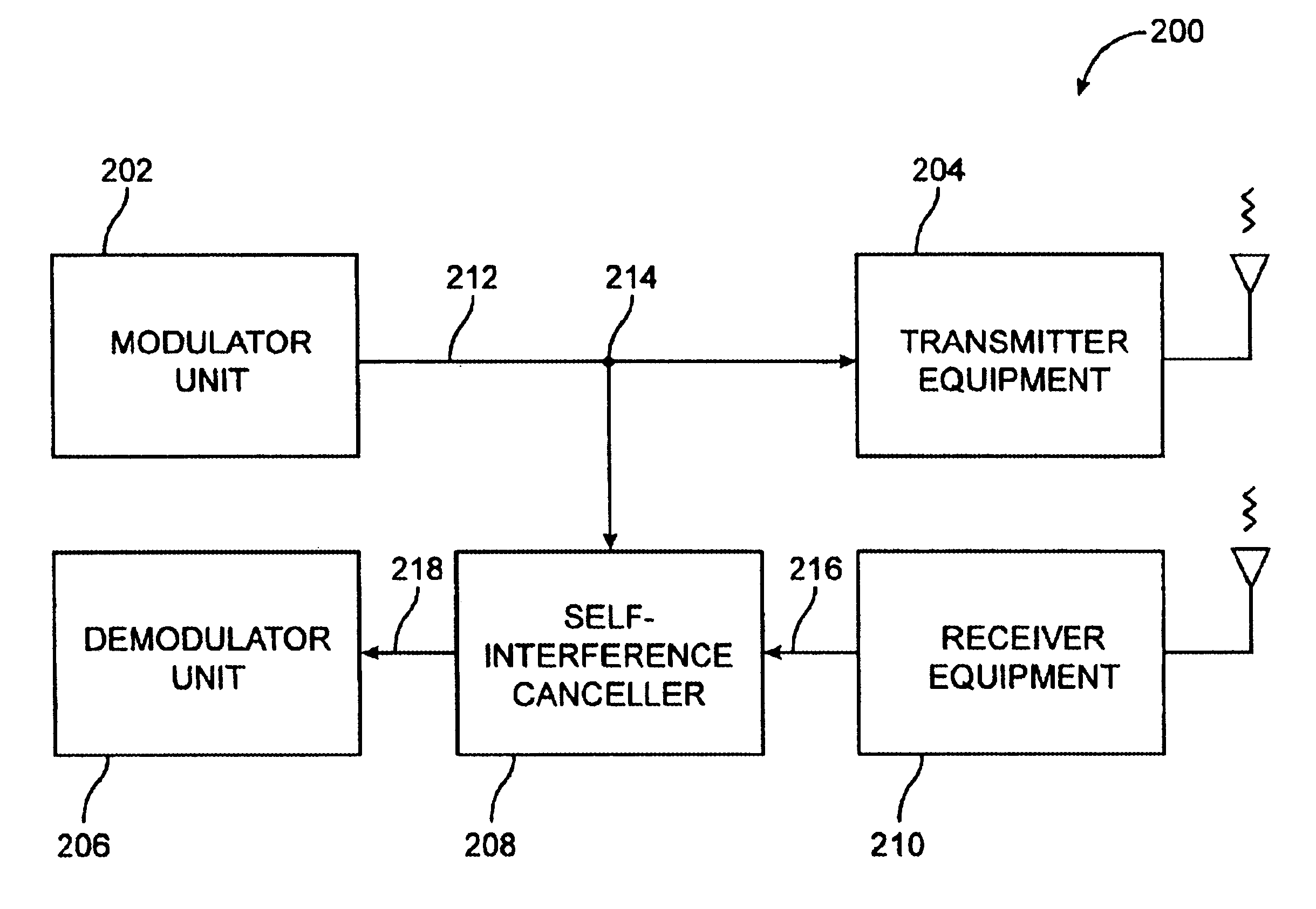
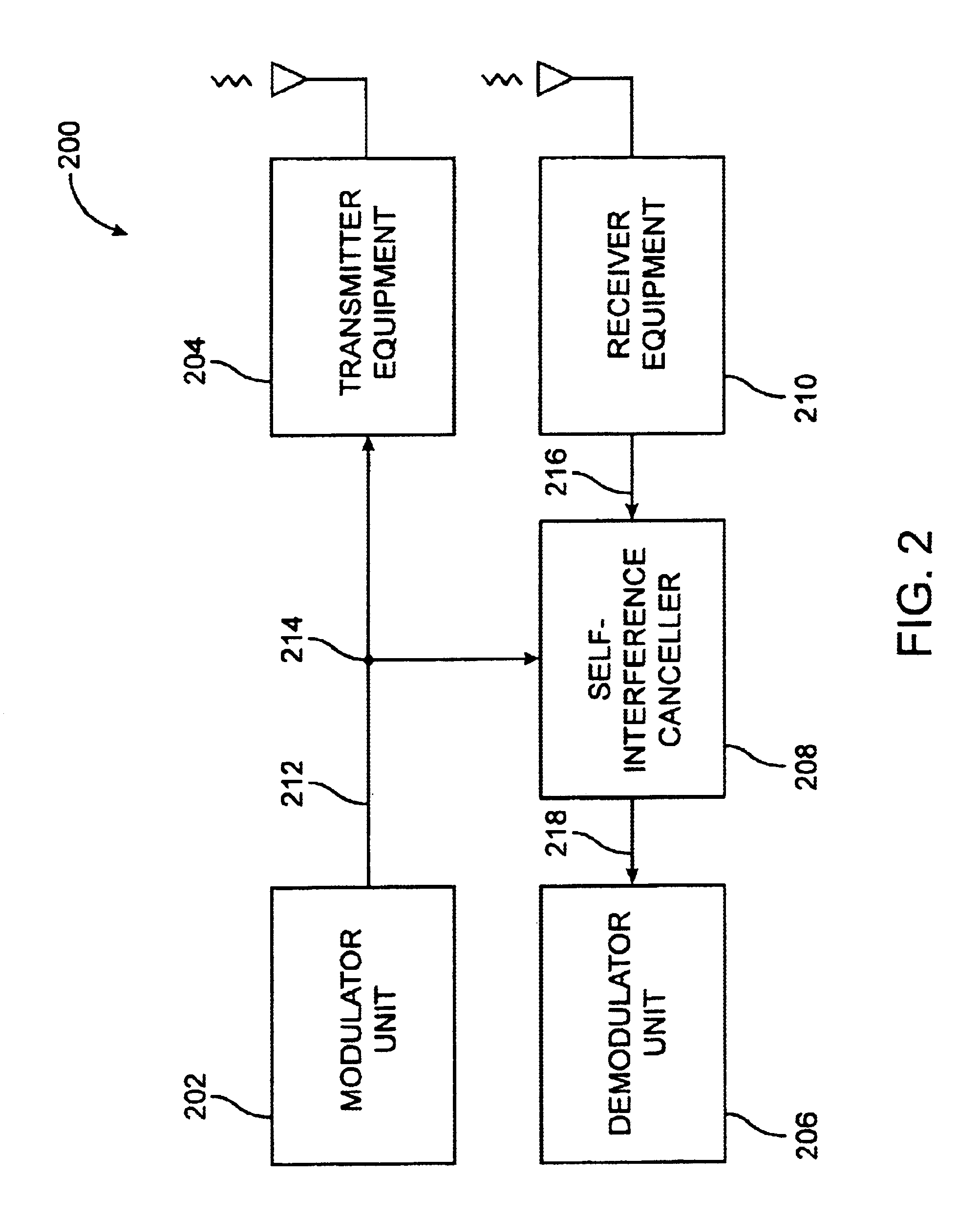
[0019]FIG. 2 illustrates an embodiment of a versatile self-interference cancellation system 200 of the present invention. The self-interference cancellation system 200 comprises a modulator unit 202, transmitter equipment 204, a demodulator unit 206, a self-interference canceler 208, and receiver equipment 210.

[0020]On the transmit side, the modulator unit 202 provides a TX interface signal 212 via an accessible feed line (typically coaxial) to the transmitter equipment 204. The TX interface signal 212 is a representation of the locally modulated signal which is also called the near signal. This representation is at or near an interface frequency that is not baseband. The transmitter equipment 204 can be any equipment along the transmit path, such as an up-converter, mixer, splitter, combiner, splitter / combiner, amplifier, antenna, or the like. A signal splitter 214 in the TX interface signal line allows the TX interface signal 212 to be easily tapped for purposes of self-interferen...


PUM


Abstract

Self-interference cancellation is provided in two-way relayed electromagnetic communication between a first device and a second device through a relay station wherein a representation of a relayed composite signal above baseband and a representation of a locally modulated interface signal above baseband interact to effect the self-interference cancellation. Specifically, the composite signal, which contains a relayed version of the locally modulated (near) signal from the first device and a relayed version of a modulated far signal from the second device, is received at the first device from the relay station. The composite signal is then provided in a representation as a first interface signal at a first frequency at or above baseband to a canceler module of the first device and a representation of the modulated near signal at a second frequency above baseband is provided as a second interface signal to the canceler module. Part of the relayed version of the modulated near signal is canceled from the representation of the composite signal using the representation of the modulated near signal as provided to the canceler module to produce a third interface signal as output at a third frequency at or above baseband. The first and second frequencies may or may not be the same.

Description

CROSS-REFERENCES TO RELATED APPLICATIONS[0001]This application is related to U.S. application Ser. No. 08 / 520,868 for SELF-INTERFERENCE CANCELLATION FOR TWO-PARTY RELAYED COMMUNICATION, filed Aug. 1, 1995, now U.S. Pat. No. 5,596,439, issued Jan. 21, 1997 and U.S. application Ser. No. 09 / 009,573 for SELF-INTERFERENCE CANCELLATION FOR RELAYED COMMUNICATION NETWORKS, filed Jan. 20, 1998, now U.S. Pat. No. 6,011,952, issued Jan. 4, 2000, both of which are owned by the Assignee of the present invention and are herein incorporated by reference for all purposes.STATEMENT AS TO RIGHTS TO INVENTIONS MADE UNDER FEDERALLY SPONSORED RESEARCH OR DEVELOPMENT[0002]Not ApplicableREFERENCE TO A “SEQUENCE LISTING,” A TABLE, OR A COMPUTER PROGRAM LISTING APPENDIX SUBMITTED ON A COMPACT DISK[0003]Not ApplicableBACKGROUND OF THE INVENTION[0004]This invention relates to a radio frequency or optical communication system in which a relay station is used to aid communication among a network of parties, and...

Claims


Application Information

Patent Timeline
IPC IPC(8): H04B1/52H04B1/50H04L25/52
CPCH04B1/525H04B7/2606H04B7/15585
Inventor BLOUNT, RICHARDMILLER, MARKMURPHY, JAMES
Owner VIASAT INC
Why Eureka
Try Eureka