Apparatus and method for detecting display mode

Inactive Publication Date: 2005-08-09
SAMSUNG ELECTRONICS CO LTD
View PDF16 Cites 51 Cited by
  • Summary
  • Abstract
  • Description
  • Claims
  • Application Information

AI Technical Summary

Benefits of technology

[0015]It is preferable that in the step (b), an analogue display mode or a digital display mode in which the difference of number of clock pulses generated at the bandwidth of the horizontal synchronous signal is detected, and the number of clock pulses counted at the bandwidth of the horizontal synchronous signal in the analogue display mode is smaller than the number of clock pulses counted at the bandwidth of the horizontal synchronous signal in the digital display mode.

Problems solved by technology

However, many times, due to wrong design of the controller 11, the mode select signal input by the user does not coincide with the mode control signal output from the controller 11.

Method used


Image

  • Apparatus and method for detecting display mode
  • Apparatus and method for detecting display mode
  • Apparatus and method for detecting display mode

Examples


first embodiment

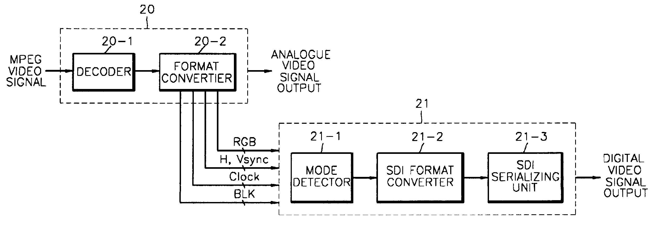
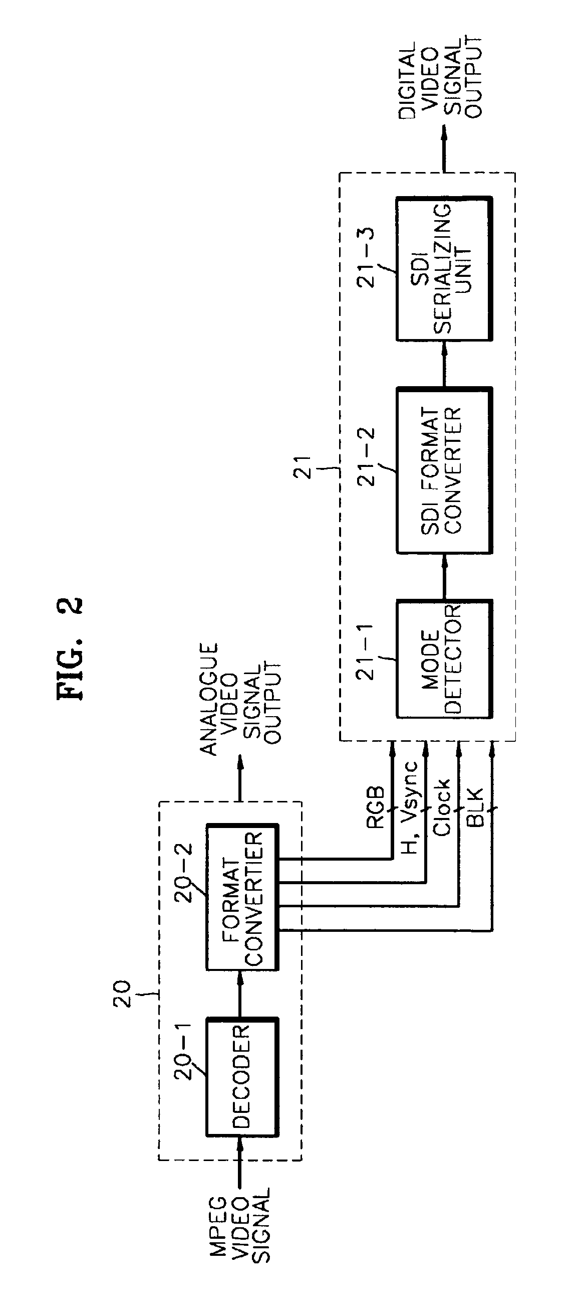
[0028]In the method for detecting a display mode by counting clock pulses generated between the present horizontal synchronous signal and the next horizontal synchronous signal according to the present invention, in step 30, a decoded video signal having a predetermined format is received. The decoder 20-1 decodes the input MPEG video signal, and the format converter 20-2 converts the formats of the decoded video signal into the format of a 1080i and 270p. The format converter 20-2 outputs a RGB (or YPbPr) signal, a clock signal CLK, a horizontal synchronous signal Hsync, a vertical synchronous signal Vsync, and a blank signal BLK, and the SDI processor 21 receives signals output from the format converter 20-2.

[0029]In step 31, the mode detector 22-1 counts clock pulses for the duration in which the horizontal synchronous signal is generated. The mode detector 22-1 counts clock pulses for the duration in which the horizontal synchronous signal from various signals output from the fo...

second embodiment

[0033]In the method for detecting a display mode by counting clock pulses generated at the bandwidth of the horizontal synchronous signal according to the present invention, in step 40, a decoded video signal having a predetermined format is received. The decoder 20-1 decodes the input MPEG video signal, and the format converter 20-2 converts the formats of the decoded video signal into the format of a 1080i and 720p mode. The format converter 20-2 outputs a RGB (or YPbPr) signal, a clock signal CLK, a horizontal synchronous signal Hsync, a vertical synchronous signal Vsync, and a blank signal BLK, and the SDI processor 21 receives signals output from the format converter 20-2.

[0034]In step 41, the mode detector 22-1 counts clock pulses for the duration in which the horizontal synchronous signal is generated. The mode detector 22-1 counts clock pulses for the duration in which the horizontal synchronous signal from various signals output from the format converter 20-2 is generated. ...


PUM


Abstract

An apparatus and method for automatically detecting a display mode to be used in a serial data interface (SDI) of a decoded video signal is provided. The apparatus for detecting a display mode includes a mode detector which detects a predetermined display mode by counting clock pulses generated between a present horizontal synchronous signal and a next horizontal synchronous signal from input decoded video signals, and a signal processing unit which converts formats of the decoded video signals so as to correspond to a display mode detected by the mode detector, serializes and outputs the decoded video signal. By deleting a control signal indicating a display mode, a control signal that does not coincide with processed data as a result of an incorrectly or incompatibly designed controller can be prevented.

Description

BACKGROUND OF THE INVENTION[0001]1. Field of the Invention[0002]The present invention relates to the field of display apparatuses and methods, and more particularly, to an apparatus and method for automatically detecting a display mode to be used in a serial data interface (SDI) of a decoded video signal. The present application is based on Korean Patent Application No. 2001-61037, filed Sep. 29, 2001, which is incorporated herein by reference.[0003]2. Description of the Related Art[0004]FIG. 1 is a block diagram illustrating the structure of a conventional apparatus for detecting a display mode. Referring to FIG. 1, the conventional apparatus for detecting a display mode includes a video processor 10, a controller 11, and a serial data interface (SDI) processor 12. The video processor 10 decodes an input MPEG video stream, converts the format of the input MPEG video stream into the format of a 1080i or 720p mode and transmits a parallel digital video signal to the SDI processor 12....

Claims


Application Information

Patent Timeline
Patent Type & Authority Patents(United States)
IPC IPC(8): H04N5/44H04N5/46H04N21/236H04N21/434
CPCH04N21/440218H04N21/4305H04N5/46H04N7/012H04N21/4342H04N21/23602H04N5/44
Inventor LEE, YOON-NAMHONG, JOO-SUN
Owner SAMSUNG ELECTRONICS CO LTD
Why Eureka
Try Eureka