Retrofittable severe duty seal for a shaft

Inactive Publication Date: 2006-01-31
DICHTOMATIK AMERICAS
View PDF209 Cites 21 Cited by
  • Summary
  • Abstract
  • Description
  • Claims
  • Application Information

AI Technical Summary

Benefits of technology

[0037]It is to be understood, as well, that many different formulations of the elastomeric, or rubberized, elements may function satisfactorily. Viton®, nitrite, carboxylated nitrite, polyacrylate, ACM, fluroelastomers, and silicone compounds are known to provide useful operational charac

Problems solved by technology

It is known by those in the art that dual cone face shields have disadvantages that significantly restrict their use.
They are simply too big to fit all of the machine locations where their superior performance co

Method used


Image

  • Retrofittable severe duty seal for a shaft
  • Retrofittable severe duty seal for a shaft
  • Retrofittable severe duty seal for a shaft

Examples


Embodiment Construction

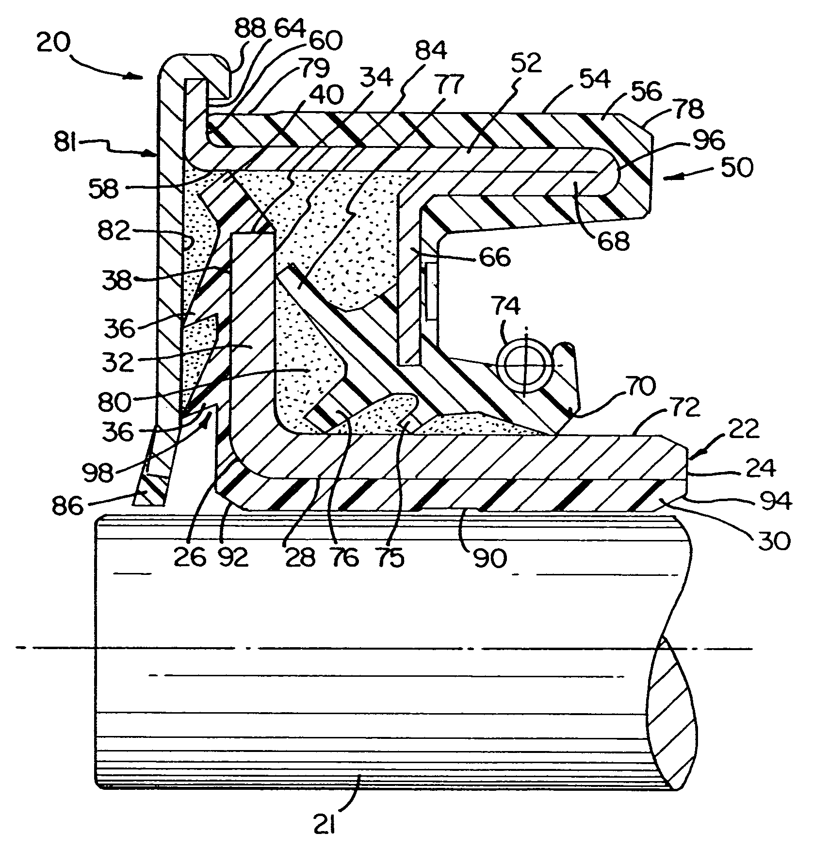
[0042]Referring now to the various figures of the accompanying drawing, FIG. 1 depicts a cross-sectional profile of an embodiment of the retrofittable severe duty seal 20 fitted onto a shaft 21. A cylindrical sleeve 22 is disposed coaxially over the shaft. The sleeve inner end 24 extends into the sealed region, normally a housing or containment for oil or grease for lubricating gears or bearings. To simplify nomenclature in this specification, the side or end or surface of a component that is oriented toward the lubricants, lubricated components, or other media from which it is desired to exclude dust, water, mud, and other environmental contaminants may be referred to using the terms “inner,”“inward,”“inside,” and similar terms. The words “outer,”“outward,”“outside” and similar terms may be used to refer to the side, or end or surface of a component that is oriented away from the sealed region, toward the exterior of a housing, or toward the unsealed overall environment into which ...


PUM


Abstract

A unitary sleeve lip seal can be used to provide permanently lubricated sealed bearings in severe service conditions such as the track pins of track-driven vehicles and agricultural equipment. The seal has a labyrinthine exclusion path and multiple dust lips contacting the sleeve in addition to the main sealing lip. A garter spring encircling the main sealing lip may enable the seal to operate at moderately elevated pressures. The sleeve has a radial flange at the outermost end. Elastomeric lips extend between the sleeve flange and a faceplate that terminates the outside end of the seal housing. The seal is packed with water-resistant grease and can, when installed in association with grease-packed bearings can create a permanently lubricated bearing/shaft assembly that requires no re-greasing. Resilient coatings both protect the sleeve and case and also improve leak resistance, especially when the seal is retrofitted onto shafts that have been damaged. The design provides a seal having performance that is comparable to that of dual cone face seals at a much lower cost and in a much smaller assembly. Seals made according to this design can easily be made in standard sizes that can serve as direct replacements for previously available seals.

Description

PRIORITY[0001]This application is a continuation of U.S. application Ser. No. 10 / 173,250, filed Jun. 17, 2002, now U.S. Pat. No. 6,726,212 which is a continuation of U.S. application Ser. No. 09 / 690,524, filed Oct. 17, 2000, now U.S. Pat. No. 6,406,026, issued Jul. 18, 2002, which is a continuation of U.S. application Ser. No. 08 / 937,427, filed Sep. 25, 1997, now U.S. Pat. No. 6,186,507, issued Feb. 13, 2001, all of which are incorporated herein by reference in their entirety.TECHNICAL FIELD[0002]The present disclosure is related to the field of seals for sealing rotary shafts, generally. The methods and apparatus are particularly related to the field of unitary combination lip and sleeve seals. More specifically, this is an improved seal adapted for use in severe duty applications including construction equipment, agricultural machinery, track driven vehicles, and other applications where oil or grease must be held in contact with rotary shaft and bearing assemblies. This seal and ...

Claims


Application Information

Patent Timeline
IPC IPC(8): F16J15/34F16J15/32
CPCF16J15/3256F16J15/324
Inventor OLDENBURG, MICHAEL R.
Owner DICHTOMATIK AMERICAS
Why Eureka
Try Eureka