Underwater riprap foundation and consolidation smoothing method therefor

a technology of underwater riprap and consolidation, which is applied in the direction of caissons, marine site engineering, construction, etc., can solve the problems of excessively high degree of consolidation, low execution efficiency, and excessively high degree of accuracy of underwater riprap foundation, so as to reduce the amount of ripraps and construct efficiently.

Active Publication Date: 2006-02-14
SAITO KIYOSHI
View PDF14 Cites 4 Cited by
  • Summary
  • Abstract
  • Description
  • Claims
  • Application Information

AI Technical Summary

Benefits of technology

[0009]It is an object of the present invention to provide an underwater riprap f

Problems solved by technology

However, within another range of the same horizontal portion within which only mulch blocks or like elements which provide a low load are to be supported, there is no problem even if the consolidation degree is lower than that where the region in which the load is high, and an error of approximately ±30 cm is permitted.
Further, for a face of slope, also an error of approximately ±50 cm is permitted.
However, since conventionally an entire underwater riprap foundation is consolidated to a degree substantially equal to that required for a region in which the load is high and is smoothed to an accuracy substantially equal to that required for the region in which the load is high, also within a region within which the load is low and a face of slope, the underwater riprap foundation is consolidated to an excessively high degree of consolidation and smoothed to an excessively high degree of ac

Method used


Image

  • Underwater riprap foundation and consolidation smoothing method therefor
  • Underwater riprap foundation and consolidation smoothing method therefor
  • Underwater riprap foundation and consolidation smoothing method therefor

Examples


Embodiment Construction

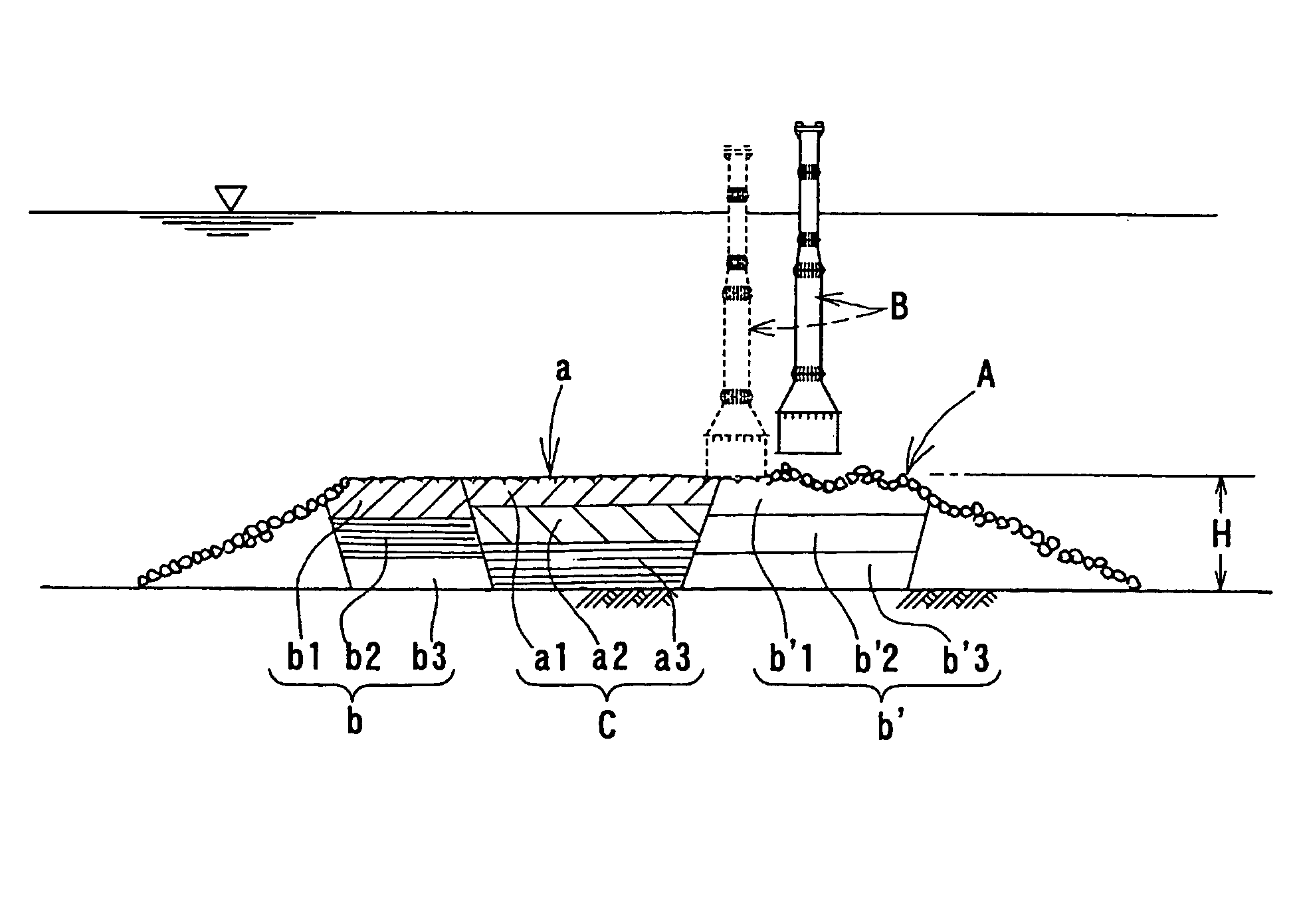
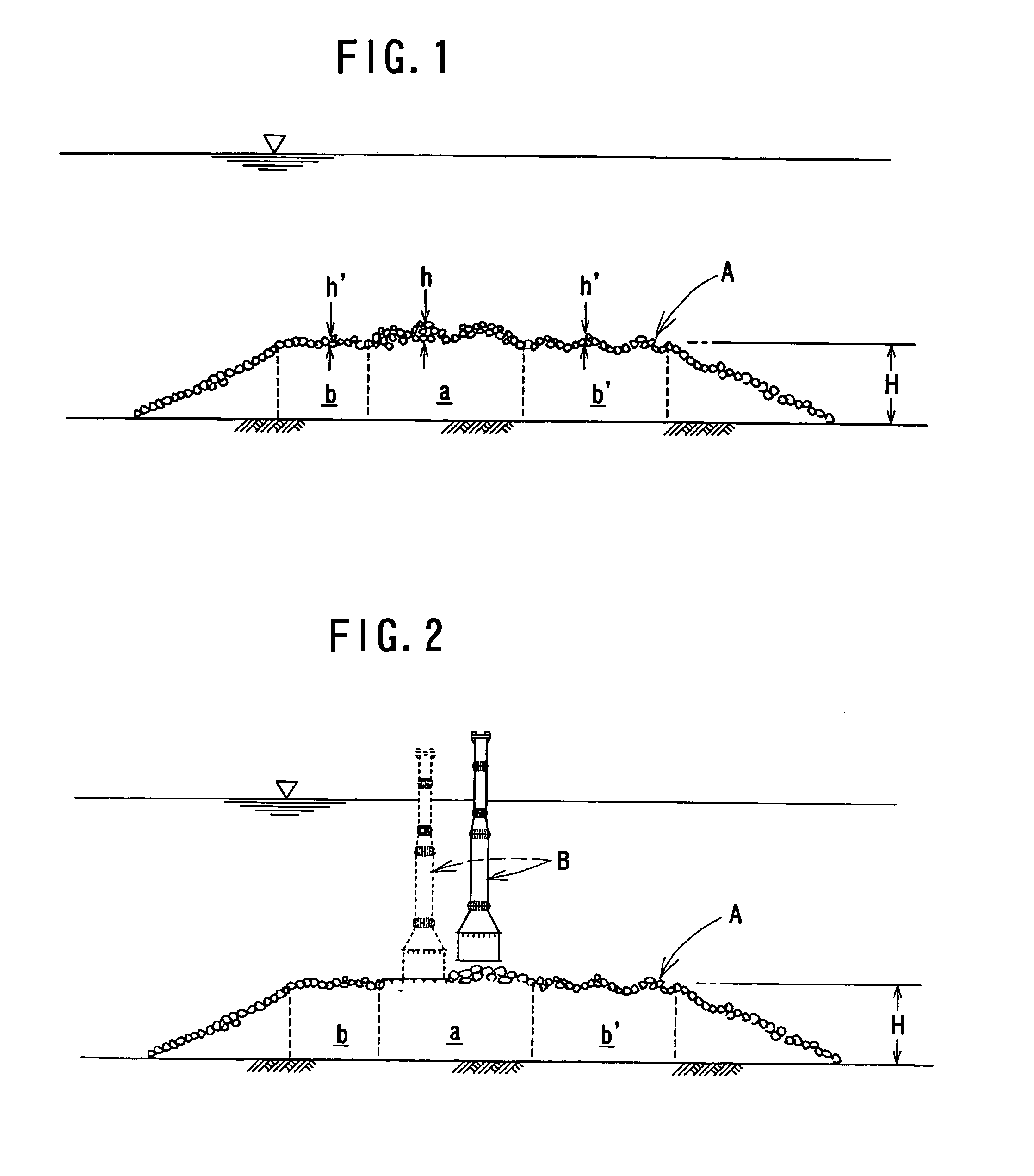
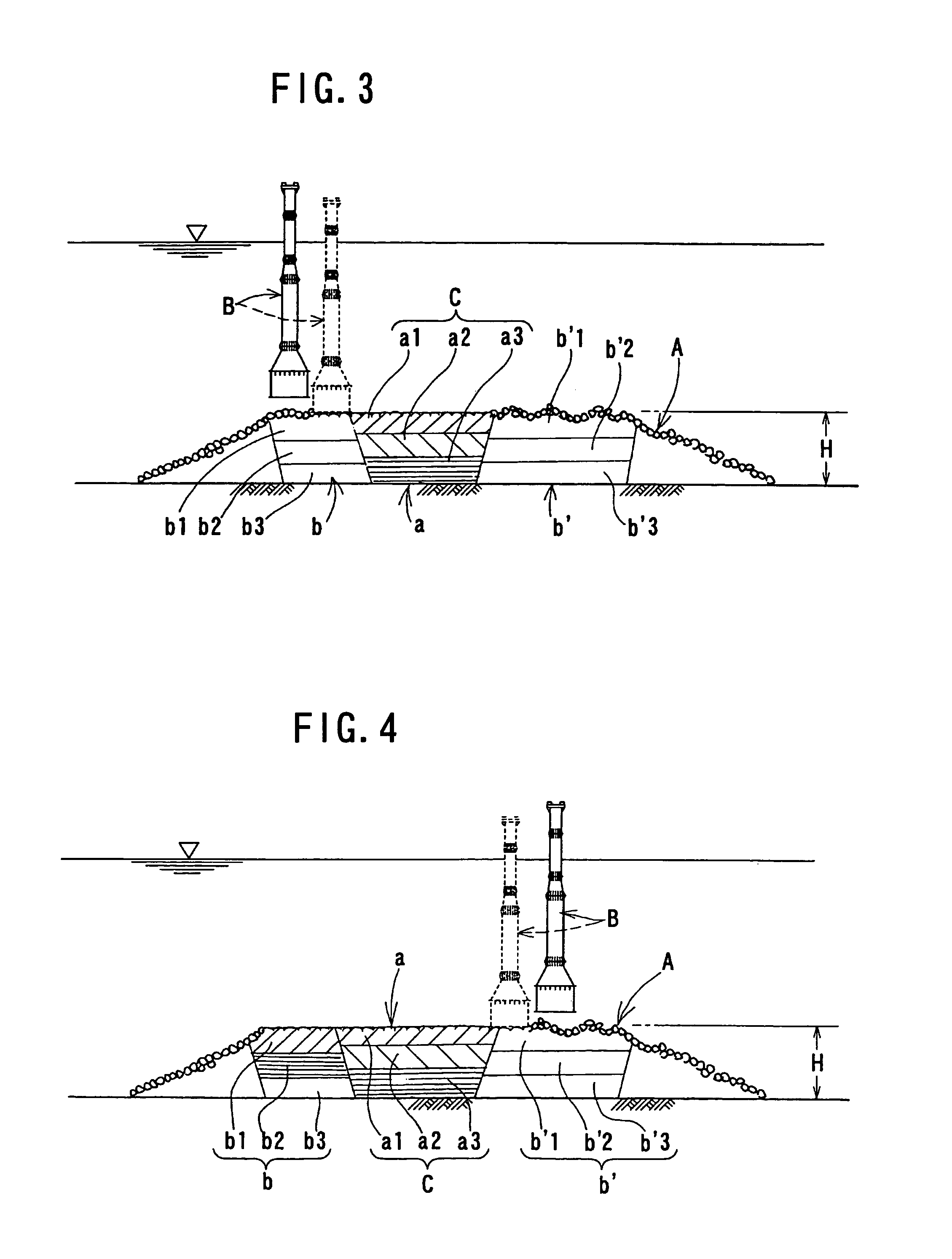
[0028]Referring first to FIG. 5, there is shown an underwater riprap foundation to which the present invention is applied. The underwater riprap foundation includes a first region a for supporting comparatively high load applied thereto from a structure such as a caisson placed thereon, and a second region b or b′ positioned adjacent the first region a for supporting comparatively low load applied thereto from mulch blocks E or the like. The first region is formed as a rigid riprap core wall body C having a consolidation density higher than that in the second region b or b′. Further, the first region a and the second region b or b′ have top faces which are flush with each other.

[0029]According to the present invention, the underwater riprap foundation described above is constructed in the following manner. In particular, referring to FIG. 1, according to the underwater riprap foundation consolidation smoothing method to which the present invention is applied, a large number of middl...


PUM


Abstract

An underwater riprap foundation which can be constructed efficiently using a reduced amount of ripraps and a consolidation smoothing method for efficient construction of the same are disclosed. The underwater riprap foundation includes a first region for supporting comparatively high load from a structure such as a caisson, and a second region positioned adjacent the first region for supporting comparatively low load from mulch blocks or the like. The first region is formed as a rigid riprap core wall body having a consolidation density higher than that in the second region. The first and second regions have top faces flush with each other. In construction, ripraps are thrown into water such that the extra-banking height in the first region is higher than in the second region, and free fall of a weight is repetitively carried out to the first and second regions to consolidate the ripraps.

Description

BACKGROUND OF THE INVENTION[0001]1. Field of the Invention[0002]The present invention relates to an underwater riprap foundation and a consolidation smoothing method therefor.[0003]2. Description of the Related Art[0004]Conventionally, an underwater riprap foundation consolidation smoothing method of the weight free fall type is known and used for construction of a mole, a quay or the like. According to the underwater riprap foundation consolidation smoothing method, ripraps are thrown into the water so as to be piled up under the water to form an underwater riprap foundation having a trapezoidal transverse section and a height greater by a required extra-banking height than a planned height for the top end. Further, free fall of a weight is carried out repetitively to consolidate and smooth the underwater riprap foundation to the planned top end height. The underwater riprap foundation consolidation smoothing method is disclosed, for example, Japanese Patent No. 2,893,527 (hereinaf...

Claims


Application Information

Patent Timeline
IPC IPC(8): E02D3/02
CPCE02D27/52E02D3/02
Inventor SAITO, KIYOSHI
Owner SAITO KIYOSHI
Why Eureka
Try Eureka