Method for controlling starting of an engine in a hybrid electric vehicle powertrain

a hybrid electric vehicle and powertrain technology, applied in the direction of engine starters, machines/engines, instruments, etc., can solve the problems of engine start and stop events that are unexpected to the driver, the complexity of the system, and the weight and cost may be design penalties, so as to achieve the effect of regulating smoothness

a hybrid electric vehicle and powertrain technology, applied in the direction of engine starters, machines/engines, instruments, etc., can solve the problems of engine start and stop events that are unexpected to the driver, the complexity of the system, and the weight and cost may be design penalties, so as to achieve the effect of regulating smoothness

US7013213B2Active Publication Date: 2006-03-14FORD GLOBAL TECH LLC

Image

  • Method for controlling starting of an engine in a hybrid electric vehicle powertrain
  • Method for controlling starting of an engine in a hybrid electric vehicle powertrain
  • Method for controlling starting of an engine in a hybrid electric vehicle powertrain

Examples


Embodiment Construction

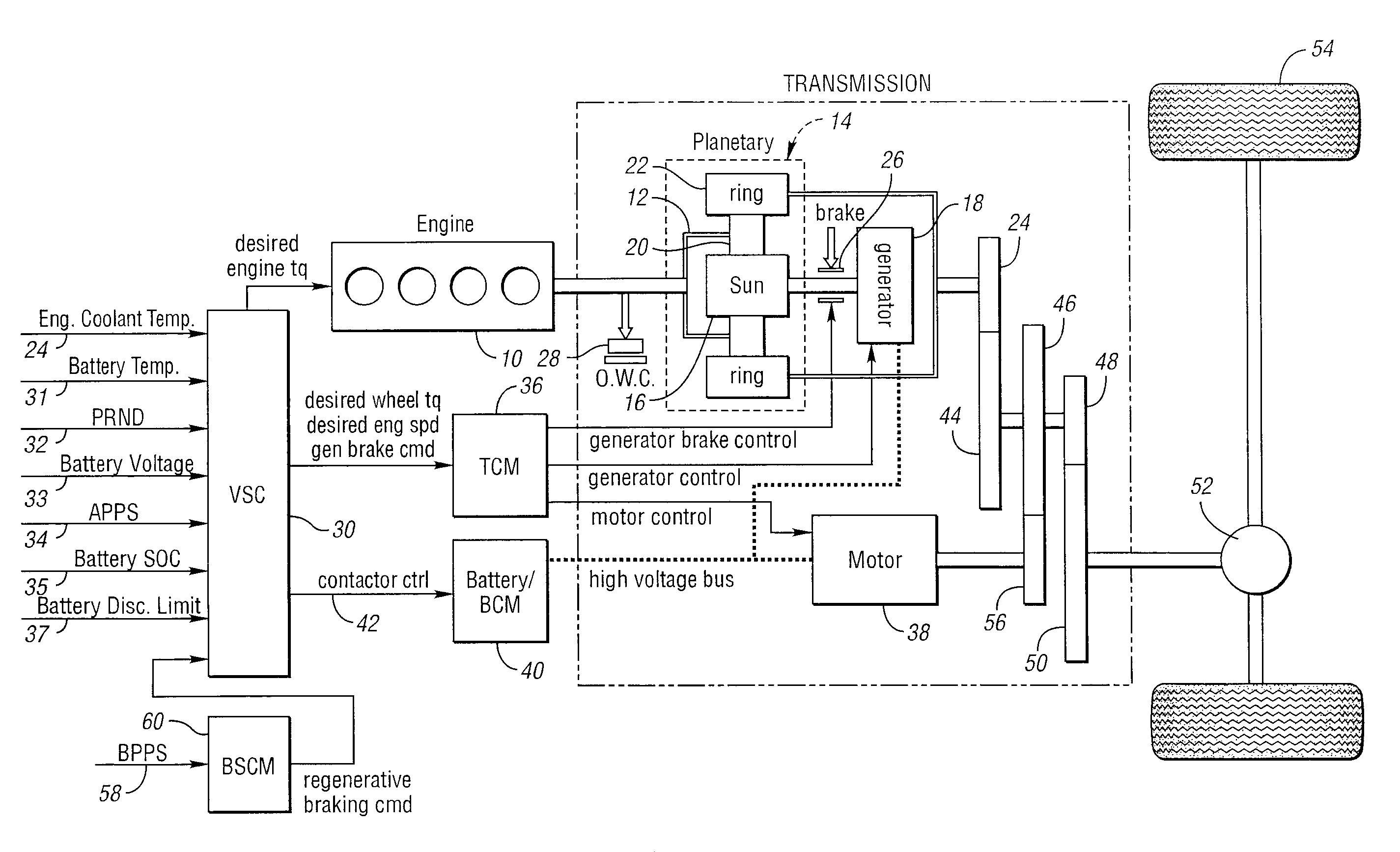
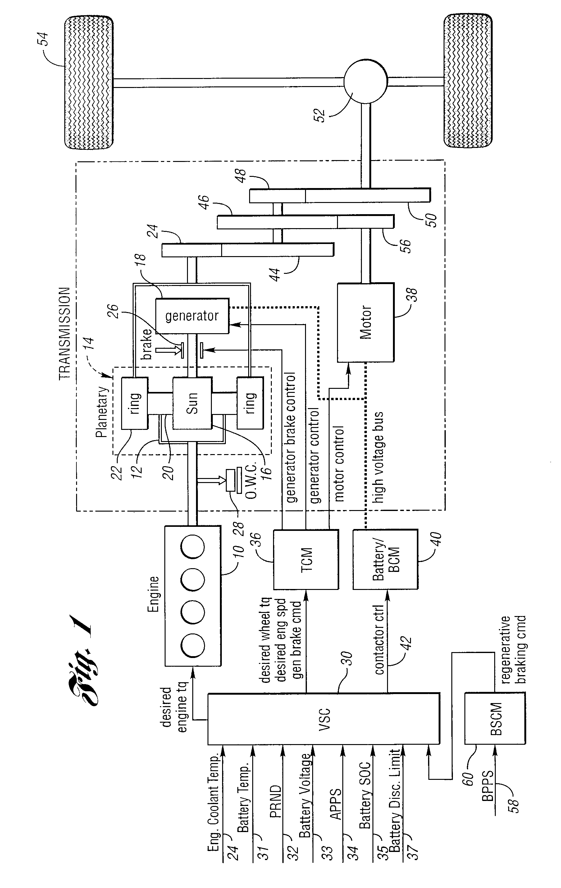
[0025]In the hybrid powertrain configuration schematically illustrated in FIG. 1, a torque output crankshaft of internal combustion engine 10 is connected drivably to carrier 12 of planetary gear unit 14. Sun gear 16 of the gear unit 14 acts as a reaction element and is drivably connected to generator 18. Carrier 12 rotatably supports planet pinions 20, which engage sun gear 16 and ring gear 22, the latter being connected drivably to transmission torque input gear 24. The generator 18 provides reaction torque when the engine delivers driving power to the transmission. The generator, which is part of a motor-generator-battery electrical subsystem, develops electrical power to complement mechanical engine power. A reaction brake 26 can be applied to establish a reaction point for the sun gear 16 and to deactivate the generator 18.

[0026]When the generator acts as a motor and the engine is de-activated, the crankshaft for the engine is braked by an overrunning coupling 28. Overrunning c...


PUM


Abstract

A method for controlling starting of an internal combustion engine in a hybrid electric vehicle powertrain having multiple power flow paths to vehicle traction wheels from the engine and from an electric motor. A smoothness factor is calculated to determine how smooth an engine start should be. Engine operating variables regulate engine smoothness during engine start events as determined by the calculated smoothness factor appropriate for selected vehicle operating conditions.

Description

BACKGROUND OF INVENTION[0001]1. Field of the Invention[0002]The invention relates to hybrid electric vehicle powertrains having an internal combustion engine and an electric motor that cooperate to provide a first power delivery mode with electro-mechanical power flow paths and a second power delivery mode in which the motor provides driving power independently of the engine.[0003]2. Background Art[0004]One class of hybrid electric automotive vehicles includes parallel-series hybrid electric vehicles. Such vehicles include a powertrain for delivering power to traction wheels from two power sources through gearing. In one powertrain configuration of this type, a combination of an internal combustion engine and a subsystem consisting of an electric motor and a generator uses a planetary gearset to define in part separate torque delivery paths to the traction wheels. The subsystem comprising the generator and the motor includes a battery, which acts as an energy storage medium.[0005]Wh...

Claims


Application Information

Patent Timeline
14 Mar 2006
Publication
US7013213B2
IPC
G06G7/70; B60K6/445; B60K6/448; B60W10/06; B60W10/08; B60W10/26; B60W20/00; B60W30/18; F02N11/00
CPC
B60K6/445; B60K6/448; B60W10/06; B60W10/08; B60W10/26; B60W30/18027; Y02T10/6239; B60W2540/10
Inventors
MCGEE, RYAN; NIESSEN, PAUL