
Method for controlling starting of an engine in a hybrid electric vehicle powertrain

a hybrid electric vehicle and powertrain technology, applied in the direction of engine starters, machines/engines, instruments, etc., can solve the problems of engine start and stop events that are unexpected to the driver, the complexity of the system, and the weight and cost may be design penalties, so as to achieve easy implementation and smooth operation

Inactive Publication Date: 2006-04-20
FORD GLOBAL TECH LLC
View PDF4 Cites 15 Cited by
  • Summary
  • Abstract
  • Description
  • Claims
  • Application Information

AI Technical Summary

Benefits of technology

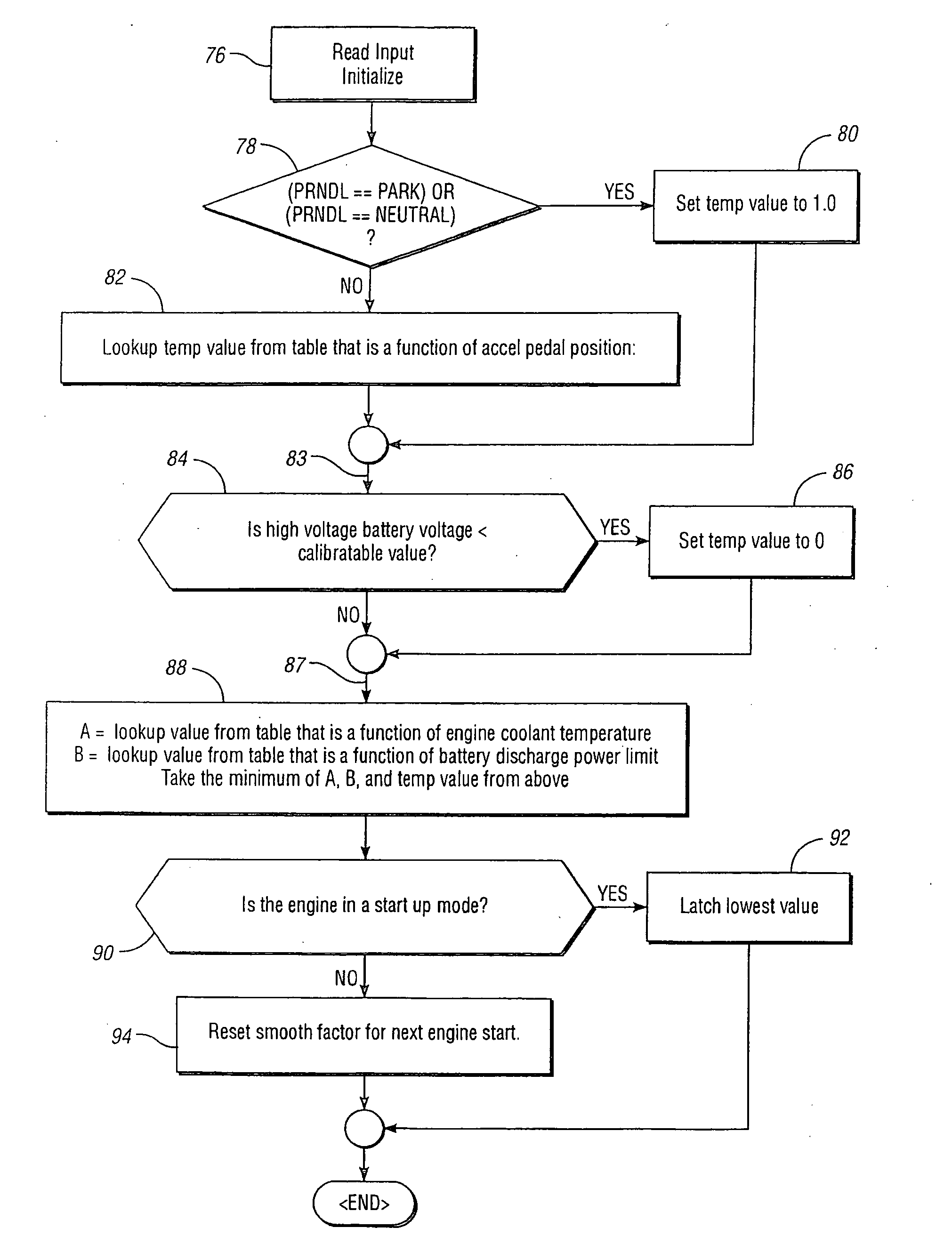
[0014] The invention includes a powertrain for a hybrid electric vehicle with a capability of starting and stopping the internal combustion engine during normal driving. The invention includes a strategy that determines an engine start smoothness factor. This is used in a control routine as a measure of how smooth an engine start should be. Using this smoothness factor, the action taken by the engine and the transmission controls will regulate smoothness. The invention allows the system to be calibrated to meet driver requirements by determining a smoothness factor that can be adjusted for different vehicles while using the same subsystem elements.
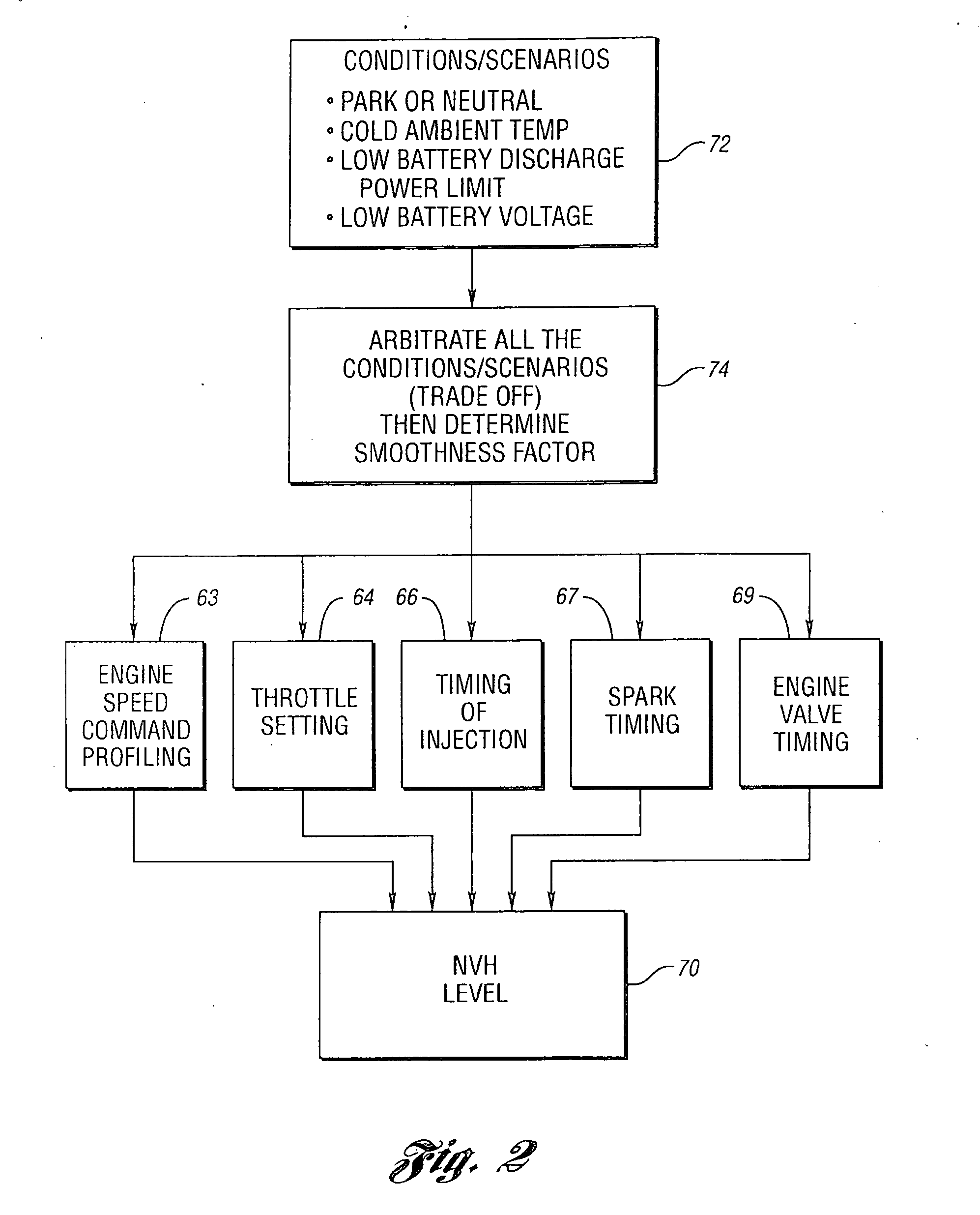
[0015] The method and strategy of the invention integrates and arbitrates in real time all driving conditions that warrant an engine start and then determines an engine start smoothness factor. The smoothness factor will dictate the control of engine operating variables, such as an engine speed command profile, an engine throttle position, fuel injection “on time” and a spark angle to achieve the desired characteristic of an engine start event; i.e., a smooth, fast or moderate engine start. Another engine operating variable could be engine valve timing. The system architecture allows the control system to be easily implemented and calibrated to meet driver requirements for any hybrid electric vehicle.

Problems solved by technology

Improved fuel economy and emissions control using a parallel-series hybrid electric powertrain configuration is achieved, however, at the expense of system complexity because of the dual power sources.
Further, weight and cost may be design penalties.
These engine start and stop events can be unexpected to the driver under certain circumstances.

Method used


Image

  • Method for controlling starting of an engine in a hybrid electric vehicle powertrain
  • Method for controlling starting of an engine in a hybrid electric vehicle powertrain
  • Method for controlling starting of an engine in a hybrid electric vehicle powertrain

Examples


Embodiment Construction

)

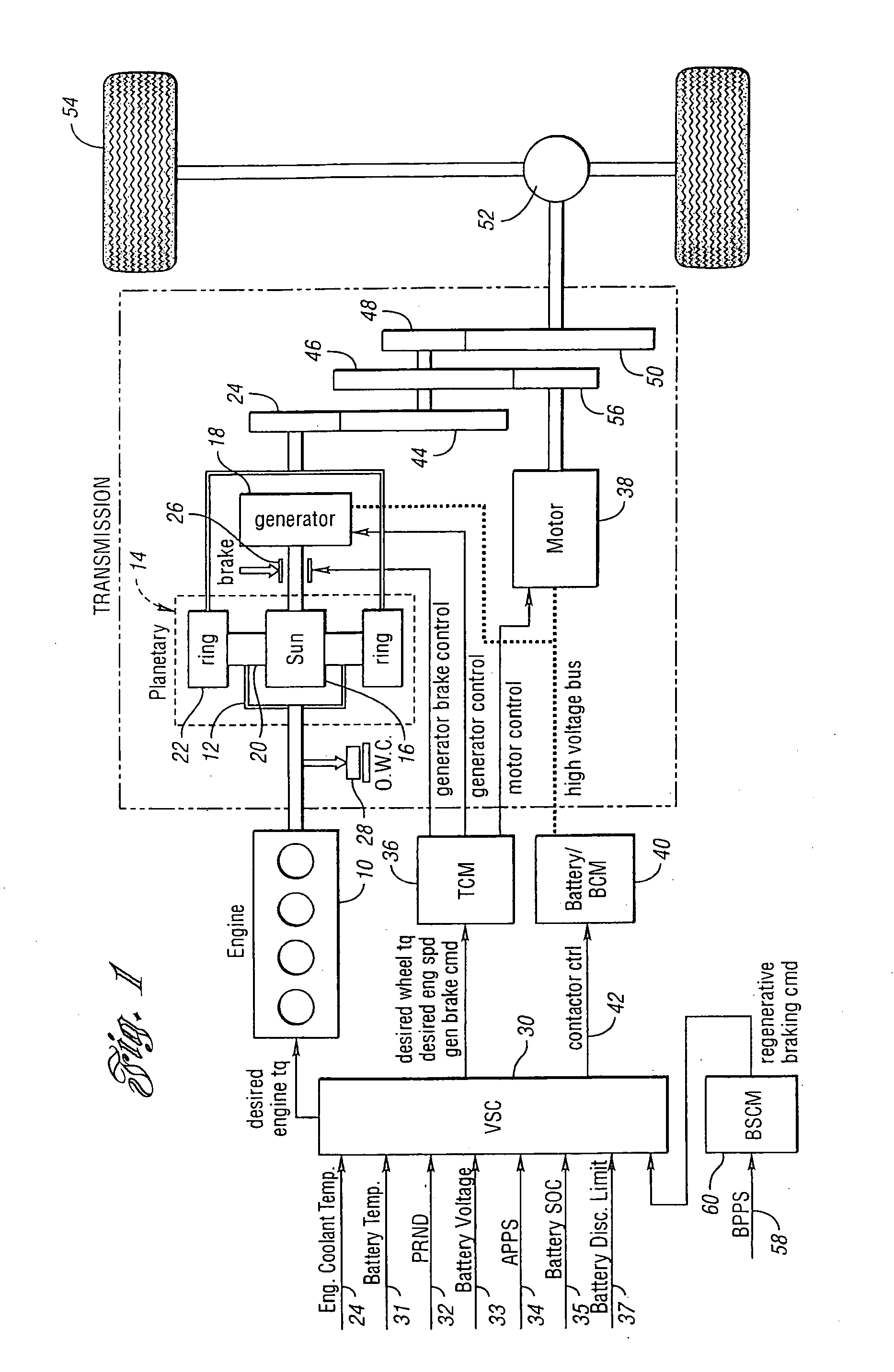
[0025] In the hybrid powertrain configuration schematically illustrated in FIG. 1, a torque output crankshaft of internal combustion engine 10 is connected drivably to carrier 12 of planetary gear unit 14. Sun gear 16 of the gear unit 14 acts as a reaction element and is drivably connected to generator 18. Carrier 12 rotatably supports planet pinions 20, which engage sun gear 16 and ring gear 22, the latter being connected drivably to transmission torque input gear 24. The generator 18 provides reaction torque when the engine delivers driving power to the transmission. The generator, which is part of a motor-generator-battery electrical subsystem, develops electrical power to complement mechanical engine power. A reaction brake 26 can be applied to establish a reaction point for the sun gear 16 and to deactivate the generator 18.

[0026] When the generator acts as a motor and the engine is deactivated, the crankshaft for the engine is braked by an overrunning coupling 28. Overrunnin...


PUM


Abstract

A method for controlling starting of an internal combustion engine in a hybrid electric vehicle powertrain having multiple power flow paths to vehicle traction wheels from the engine and from an electric motor. A smoothness factor is calculated to determine how smooth an engine start should be. Engine operating variables regulate engine smoothness during engine start events as determined by the calculated smoothness factor appropriate for selected vehicle operating conditions.

Description

CROSS-REFERENCE TO RELATED APPLICATIONS [0001] This application is a division of U.S. application Ser. No. 10 / 709,537 filed May 12, 2004. The application claims the benefit of that application.BACKGROUND OF THE INVENTION [0002] 1. Field of the Invention [0003] The invention relates to hybrid electric vehicle powertrains having an internal combustion engine and an electric motor that cooperate to provide a first power delivery mode with electromechanical power flow paths and a second power delivery mode in which the motor provides driving power independently of the engine. [0004] 2. Background Art [0005] One class of hybrid electric automotive vehicles includes parallel-series hybrid electric vehicles. Such vehicles include a powertrain for delivering power to traction wheels from two power sources through gearing. In one powertrain configuration of this type, a combination of an internal combustion engine and a subsystem consisting of an electric motor and a generator uses a planeta...

Claims


Application Information

Patent Timeline
Patent Type & Authority Applications(United States)
IPC IPC(8): F02N11/00B60K6/445B60K6/448B60W10/06B60W10/08B60W10/26B60W20/00B60W30/18G06G7/70
CPCB60K6/445B60K6/448B60W10/06B60W10/08B60W10/26B60W20/00B60W30/18027B60W2540/10F02N11/00Y02T10/6243Y02T10/6286Y02T10/6239Y02T10/62B60K2006/268B60W20/40
Inventor MCGEE, RYANNIESSEN, PAULSYED, FAZALCZUBAY, JOHNBUTCHER, JONATHANKUANG, MING
Owner FORD GLOBAL TECH LLC
Learn More