Method and system for wireless digital multimedia transmission

a digital multimedia and wireless technology, applied in the field of wireless multimedia systems, can solve the problems of requiring a relatively expensive compression module at the source and a relatively expensive decompression module at the display, and achieve the effect of minimizing differential signaling

Active Publication Date: 2006-03-28
SONY CORP +1
View PDF19 Cites 46 Cited by
  • Summary
  • Abstract
  • Description
  • Claims
  • Application Information

AI Technical Summary

Problems solved by technology

Specifically, if a wireless link such as IEEE 802.11(b, g or a) is used that has a bandwidth which is insufficient to carry uncompressed multimedia such as uncompressed high definition (HD) video, compressed multimedia video (standard definition or high definition) would have to be transmitted, requiring a relatively expensive compression module at the source and decompression module at the display.

Method used


Image

  • Method and system for wireless digital multimedia transmission
  • Method and system for wireless digital multimedia transmission
  • Method and system for wireless digital multimedia transmission

Examples


Embodiment Construction

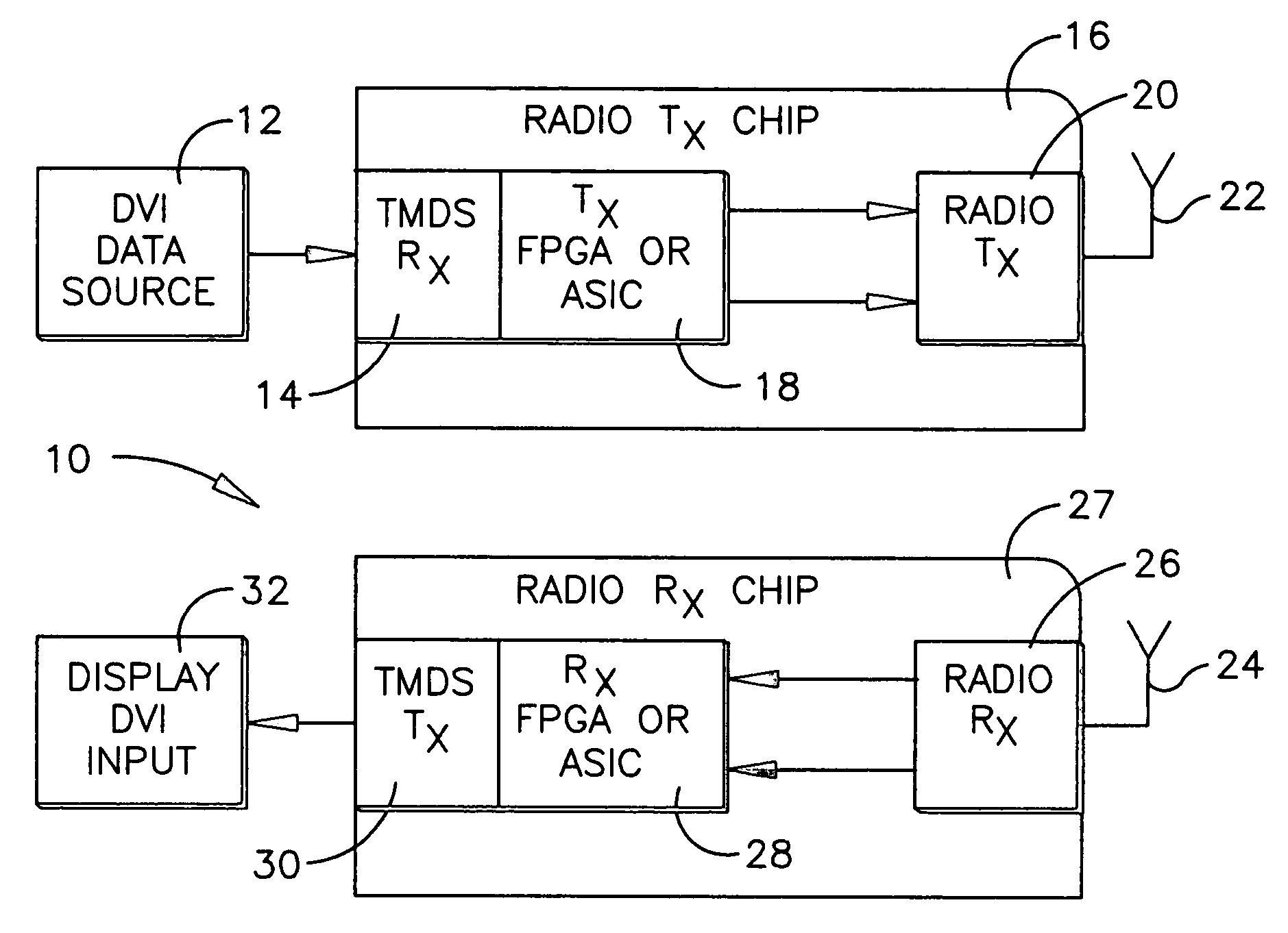
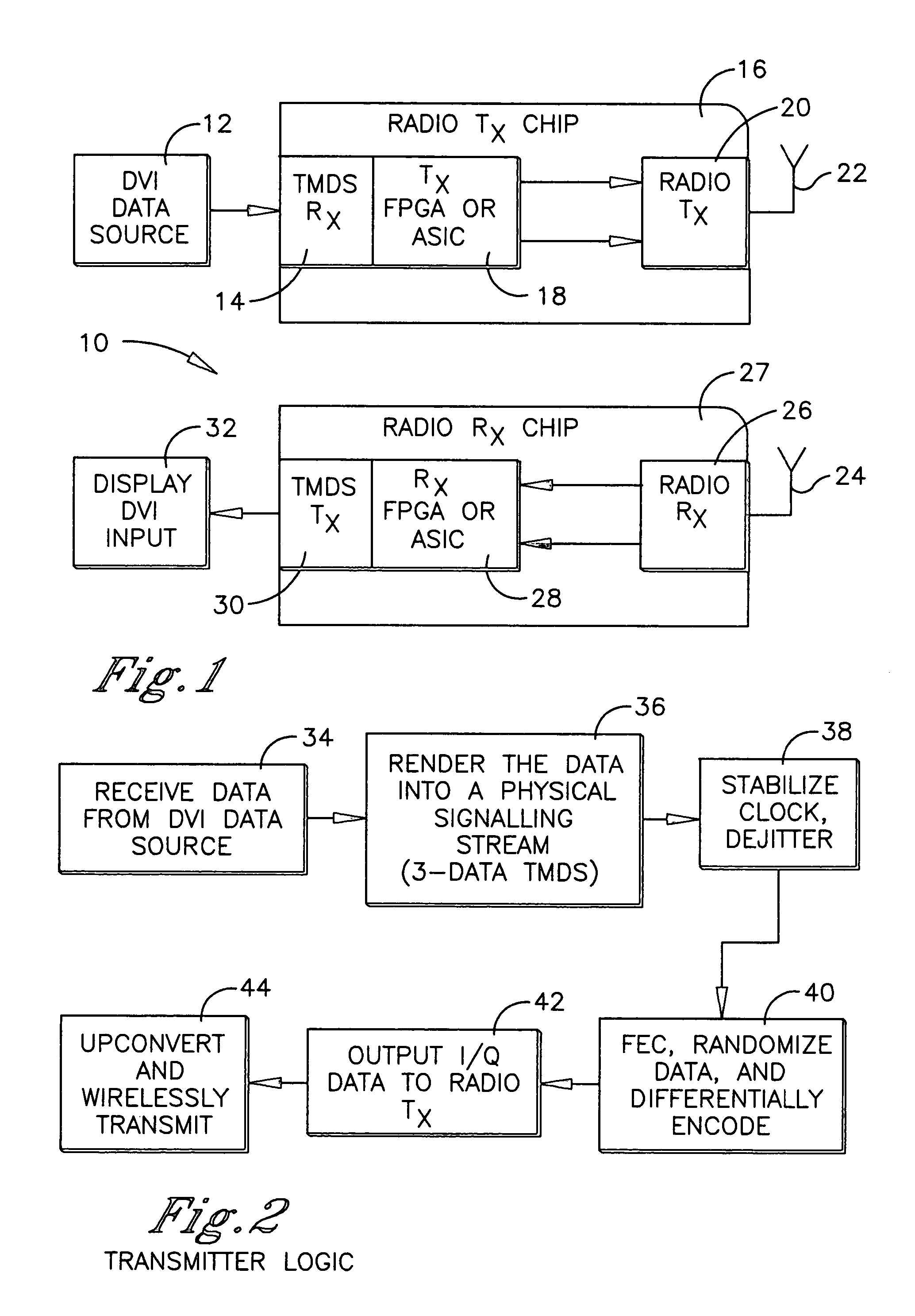
[0018]Referring initially to FIG. 1, a system is shown, generally designated 10, which includes a source 12 of Digital Visual Interface (DVI) or HDMI data that may be a set-top box, laptop computer or other multimedia computer or server. Or, it can be a satellite, broadcast, or cable receiver, or it can be a DVD player or other multimedia source.

[0019]The data is sent to a physical signaling receiver 14 of a transmitter board 16 that preferably contains all of its components on a single substrate. In the preferred embodiment, the receiver 14 is a transition minimized differential signaling (TMDS) receiver.

[0020]The output of the receiver 14 is sent to a transmitter processor 18 that can be implemented by an application specific integrated circuit (ASIC) or field programmable gate array (FPGA). The processor 18 processes the data in accordance with the disclosure below for wireless transmission by a wireless transmitter 20 over a transmitting antenna 22. As set forth further below, t...


PUM


Abstract

Digital Visual Interface (DVI), or High Definition Multi-media Interface (HDMI), data is received from a source and sent to a transmitter chip that includes a transition minimized differential signaling (TMDS) receiver that outputs a 3-data and 1-clock physical signaling stream representing the DVI or HDMI data. This stream is rendered into I and Q data by an ASIC or FPGA and sent to a wireless transmitter for modulation, upconverting, and transmission to, e.g., a nearby display device without ever rendering the data into baseband video on the transmitter chip. The display device has a receiver chip that is essentially the inverse of the transmitter chip.

Description

RELATED APPLICATIONS[0001]This application claims priority from U.S. provisional patent application Ser. No. 60 / 520,588, filed Nov. 17, 2003.FIELD OF THE INVENTION[0002]The present invention relates generally to wireless multimedia systems.BACKGROUND[0003]Digital video can be transmitted from a source, such as a computer or Set Top Box (STB), to a display, such as a video monitor or entertainment display and associated audio and control functions, using one of two protocols known as Digital Visual Interface (DVI) and High Definition Multi-media Interface (HDMI). Having been developed primarily for computers, DVI, and having been developed primarily for digital displays, HDMI are intended for wired transmission.[0004]As recognized herein, to save table space and to increase people's mobility and viewing lines in the room, it may be desirable to view the multimedia on a display using a minimum of wiring. For instance, it may be desirable to mount a projector on the ceiling or to mount...

Claims


Application Information

Patent Timeline
Patent Type & Authority Patents(United States)
IPC IPC(8): H04Q7/24H04L12/28G09G5/00H04L29/06H04W88/02
CPCG09G5/006H04L29/06027H04N21/2381H04L65/607H04N21/4381H04N21/4363H04W88/02H04L65/70H04N7/015H04L12/28H04N5/44H04L65/1101
Inventor HARDACKER, ROBERTDESCH, DAVID A.
Owner SONY CORP
Why Eureka
Try Eureka