Bath overflow alarm suitable for different installation arrangements

a technology for bath tubs and overflow alarms, applied in the direction of valves, mechanical devices, engine components, etc., can solve the problems of large direct damage to surrounding materials, damage can be caused, and the cover over the drain line is often not large enough, so as to reduce the cost of the unit, simplify the inventories, and reduce the variety of drain designs

Inactive Publication Date: 2006-08-29
HIRTRITER R ERIC
View PDF25 Cites 23 Cited by
  • Summary
  • Abstract
  • Description
  • Claims
  • Application Information

AI Technical Summary

Benefits of technology

[0013]By use of these embodiments the number of individual units needed to handle the variety of drain designs is greatly reduced, reducing cost of the unit and simplifying inventories.

Problems solved by technology

Most bathtubs are equipped with drains to prevent the overflow of the water; however, that drain line or the cover over the drain line is often not large enough to allow water to go to the drain at the rate the water is entering the bathtub.
Thus damage can be caused by the water overflowing the top of the bathtub.
The direct damage to surrounding materials can be great but the water may also provide an environment suitable for dangerous mold and mildew or create a slipping hazard when someone finally comes to turn off the water.
However, this narrow opening often limits the amount of water which can enter the piping to an amount less than that flowing into the bathtub.
As noted above, the past and present overflow plumbing designs do not allow enough volume of liquid to escape from the bathtub when the bathtub is being filled with the current overflow cover plates.
Furthermore, these cover plates and the evacuation areas on the sides of the cover plates may become blocked with a variety of things as well as just a buildup of hard water deposits.
There have been many attempts to solve overflowing of bathtubs in the past but have all met with problems.
These fail for practical purposes because people do not want the device to remain in the bathtub with them while they are relaxing and so must be removable.
There are many different type of fluid level alarms; however, none are financially feasible for the home or commercial bathtub applications.
The current designs are attached to the side of bathtubs with suction cups, so they are easily removed or stolen; attached to the wall above the bathtub and get in the way of the person bathing; uses floats which can be fouled by hard water or other debris or are hard to mount; use a diaphragm switch sensitive to pressure changes, but the rubber can wear out and not react or can leak itself, or the switch itself is buoyant, which could get stuck in the drain.
Two designs address some of the problems but create new problems.
While these designs solve some of the prior art problems, they require specific embodiments for each particular bath drain design.
This increases their cost and creates inventory problems for both the manufacturer and the retailer.

Method used


Image

  • Bath overflow alarm suitable for different installation arrangements
  • Bath overflow alarm suitable for different installation arrangements
  • Bath overflow alarm suitable for different installation arrangements

Examples


first embodiment

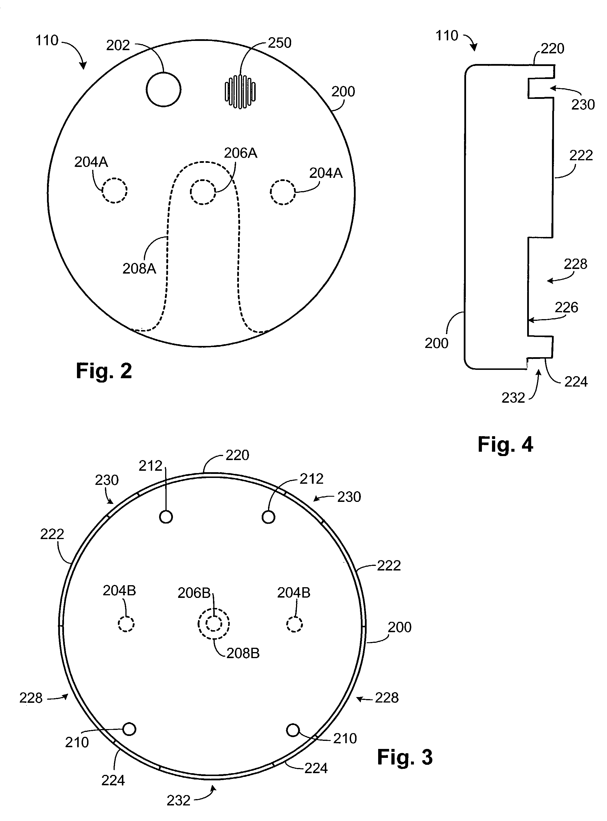
[0025]FIGS. 2–5 are drawings of various views and components of a bath overflow alarm 110 according to the present invention. FIG. 2 shows a front view of the alarm 110. An outer housing 200, preferably made of a plastic or plated metal material, is shown. An alarm test / reset button 202 is present on the front face. The button 202 is used to test the alarm 110, both for local operation and remote operation, and to reset the alarm 110 if a warning has been provided. Preferably the local operation is tested by depressing the button 202 for a first period and releasing it, while remote operation is tested by depressing the button 202 for a second period, preferably longer than the first period, and releasing it. Depressing the button 202 while an alarm condition is present resets the alarm 110. A speaker area 250 is also on the face of the alarm 110. The speaker area 250 corresponds to the location of a speaker 252 and is preferably formed from a series of grooves in the housing 200. T...

second embodiment

[0032]FIGS. 6–9 is used by first installing the adapter ring 406 to the bathtub 100. Then the housing 400 is placed over the adapter ring 406 so that the tab 408 is captured by the tang 404. Screw 410 is then inserted through hole 402 and threaded into the hole in the adapter ring 406.

[0033]An alternative adapter ring 506 is shown in FIG. 10. In this embodiment the adapter ring 506 does not contain any web elements but is extended, with the extended area 502 being threaded to mate with European and newer American threaded overflow drains. The threaded area is shown on the inside of the extended area 502 in FIG. 10 for use with European designs but could be on the outside of the extended area 502 for use with newer American designs. Alternatively, both inside and outside could be threaded to cover both cases, particularly if the adapter ring 506 is plastic. Thus, only the adapter ring 506 need changed, with the housing 400 being reusable.

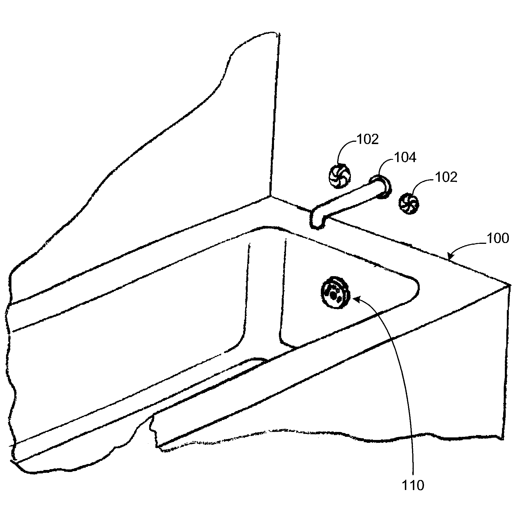
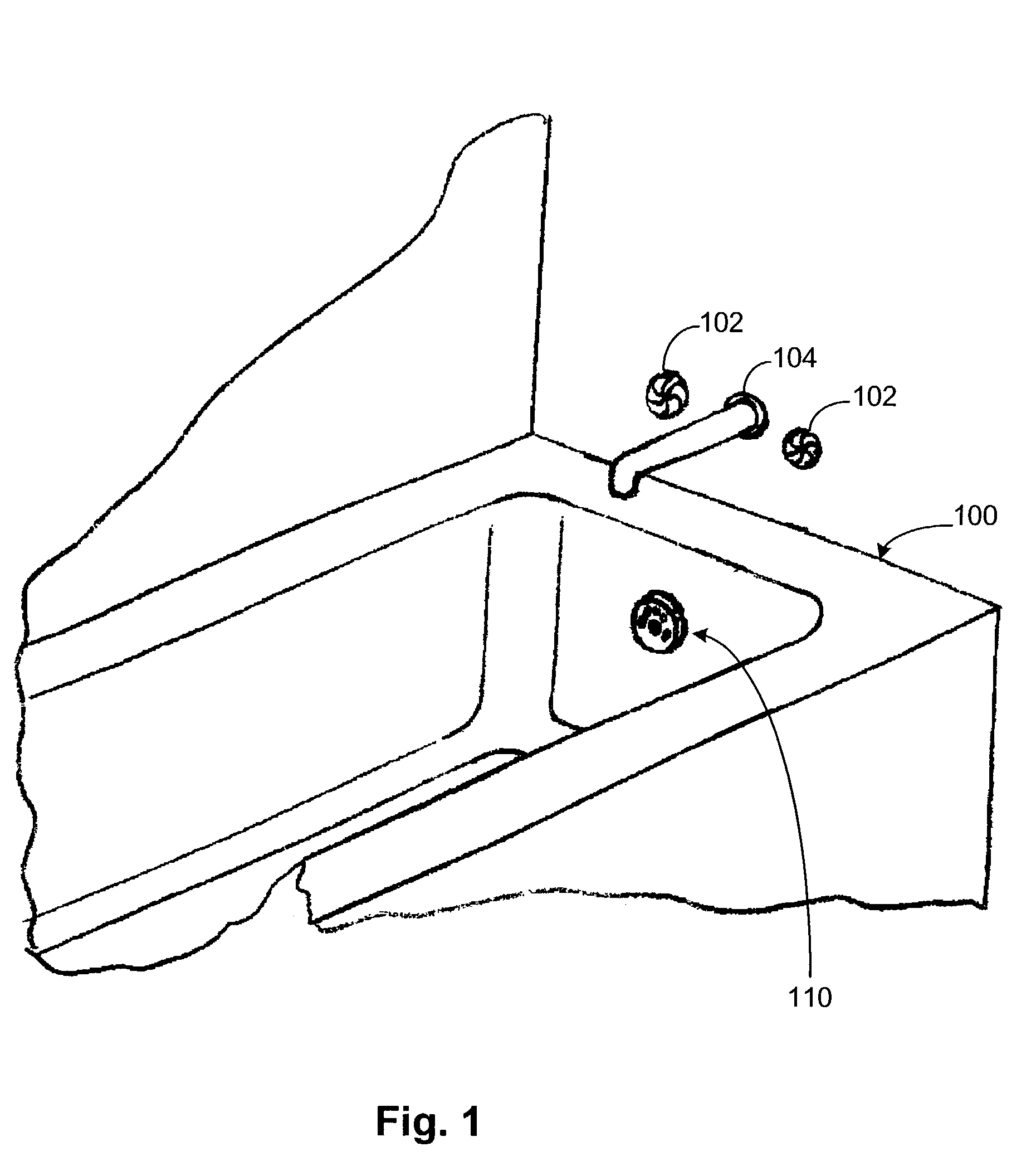
[0034]As shown, an alarm 110 replaces the exis...


PUM


Abstract

Alarms adaptable to common American bathtub cover plate configurations. Two different embodiments are illustrated. In a first embodiment, the alarm unit is designed to allow use with the three different mounting styles of cover plates used in the United States. The unit housing is preferably formed of plastic or metal with different colors and finishes and includes removable areas to allow use with a single center screw; dual screws or a center pivoting drain lever with dual screws. The various electronics components remain sealed inside the waterproof plastic or metal housing in all instances. In a second embodiment, a waterproof housing attaches to an adapter ring. The adapter ring is configured to cooperate with single center screw and dual screw variations. An alternative adapter ring can be used with European and newer American threaded overflow drains. In the first two embodiments there can be upper and lower sensor(s), preferably a pair of each, to provide initial and critical warnings. The warnings include audible warnings emitted by the alarm unit as well as transmitted signals for detection by remote devices.

Description

BACKGROUND OF INVENTION[0001]1. Field of the Invention[0002]The invention relates to a bathtub overflow alarm and more particularly pertains to alerting a user to water reaching a hazardous or dangerous level within a bathtub or other container.[0003]2. Description of the Related Art[0004]People often do other things while waiting for a bathtub to fill in order not to waste time. Sometimes they get engrossed in a different activity and forget they started the water. Most bathtubs are equipped with drains to prevent the overflow of the water; however, that drain line or the cover over the drain line is often not large enough to allow water to go to the drain at the rate the water is entering the bathtub. Thus damage can be caused by the water overflowing the top of the bathtub. The direct damage to surrounding materials can be great but the water may also provide an environment suitable for dangerous mold and mildew or create a slipping hazard when someone finally comes to turn off t...

Claims


Application Information

Patent Timeline
Patent Type & Authority Patents(United States)
IPC IPC(8): E03C1/244E03C1/24
CPCE03C1/24
Inventor HIRTRITER, R. ERIC
Owner HIRTRITER R ERIC
Why Eureka
Try Eureka