Power booster for metal disintegrator

a technology of power booster and metal disintegrator, which is applied in the direction of manufacturing tools, welding equipment, arc welding equipment, etc., can solve the problems of large isup>2/sup>r heating loss in the cutting transformer, limited metal removal rate and cross-sectional area of material being removed, etc., to simplify inventory, production and diagnostics

Active Publication Date: 2012-12-25
CAMMANN
View PDF5 Cites 0 Cited by
  • Summary
  • Abstract
  • Description
  • Claims
  • Application Information

AI Technical Summary

Benefits of technology

[0006]The ability to reliably use two disintegrator units in parallel offers many benefits as compared, for example, to a single larger unit. The total heat loss in the cutting transformer and related componentry is cut in half. Identical componentry can be used in both units thereby simplifying inventory, production, and diagnostics. Some of the components, including the cooling water circulating pump, heat exchanger, and control power supply, can be shared between the units. The units can be individually moved through passageways and into confined spaces separately where a single larger unit could not fit. Where a job has a low power requirement, only one disintegrator unit need be transported to and used at the worksite.

Problems solved by technology

The rate of metal removal and the cross-sectional area of the material being removed is limited by the power capacity of the disintegrator.
One obstacle in simply increasing the size of existing designs is that a large I2R heating loss occurs in the cutting transformer.
Dissipation of this heat already can tax the materials and construction of existing transformer arrangements to their practical limits.
Simply connecting two disintegrators in parallel for operation of a single, common electrode is problematic because different settings on their respective auto transformers and / or connections to different phases of a power supply can cause back feed into a disintegrator unit that results in damage or destruction of a unit.

Method used


Image

  • Power booster for metal disintegrator
  • Power booster for metal disintegrator
  • Power booster for metal disintegrator

Examples


Embodiment Construction

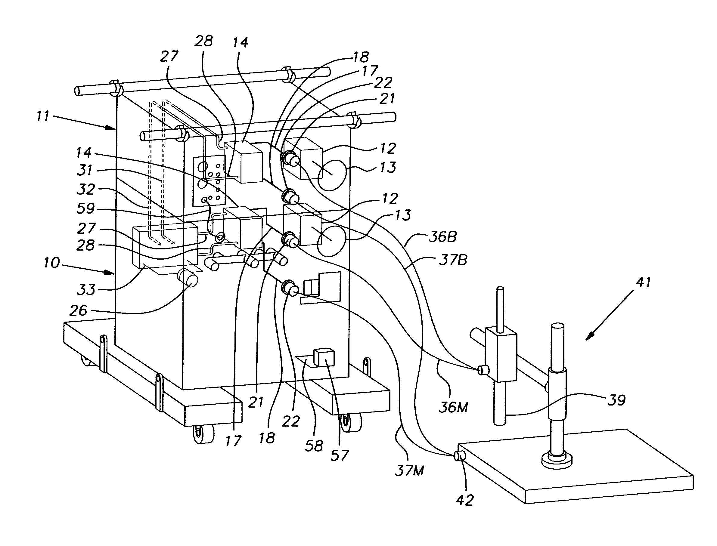
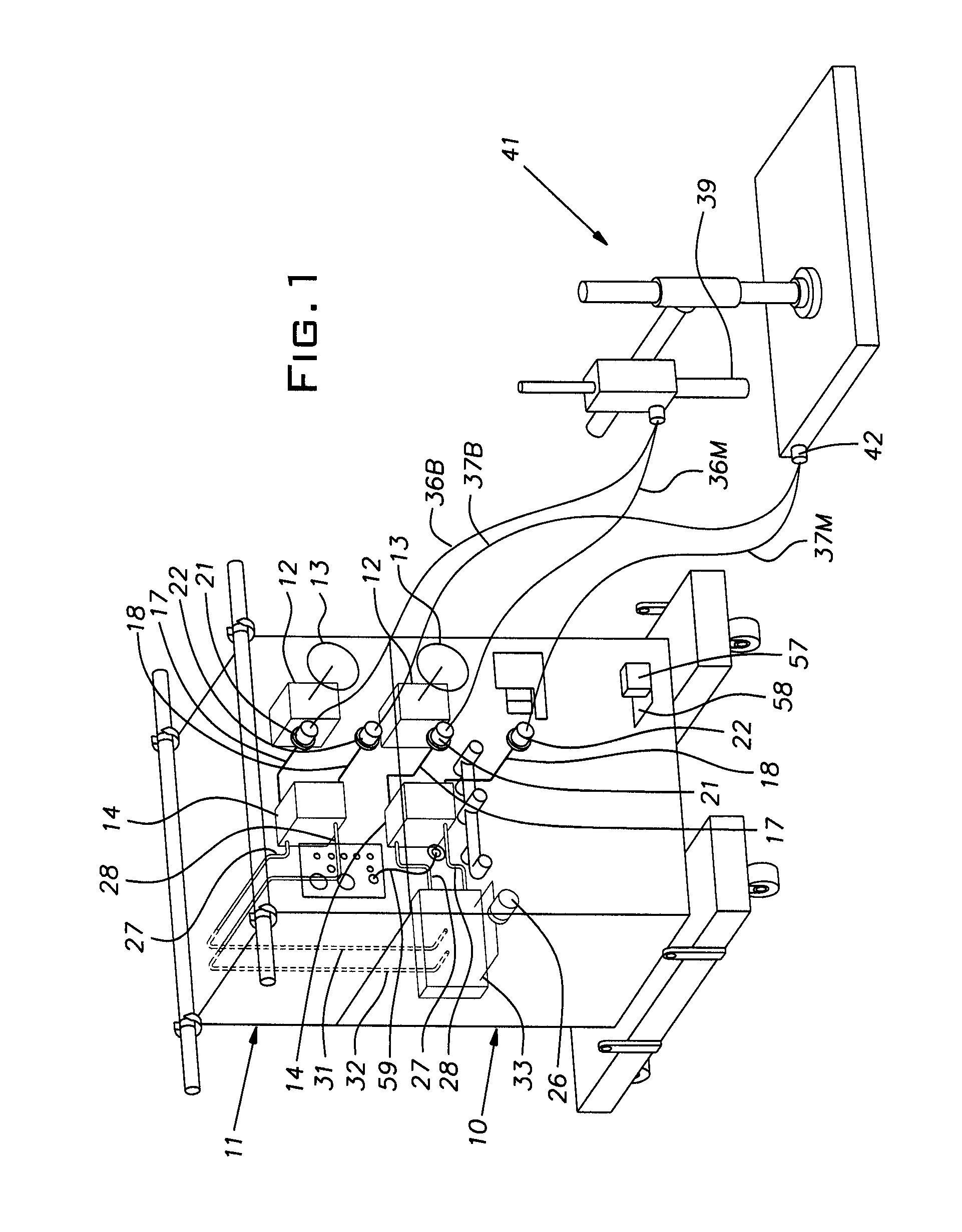
[0009]Referring now to FIG. 1, a master or host disintegrator unit 10 and a power booster disintegrator unit 11 are shown. The units 10, 11 comprise separate metal cabinets in each of which are mounted electrical and electronic components (hereafter each referred to as electrical components). Electrical components discussed below in the units 10, 11 that are identical are identified by the same numerals. Multi-tap auto-transformers 12 are each manually set by rotating a knob 13 on the front of the respective unit 10, 11. The auto-transformers 12 drive their respective cutting transformers 14 such that a cutting transformer will develop, for example, 3 to 30 volts in 8 steps or settings of an auto-transformer. Secondary windings 16 of the cutting transformers 14 as well as lines 17, 18 connecting the winding to output and ground terminals or sockets 21, 22 can comprise double wall copper tubing for supply and return of water coolant.

[0010]An electrically operated pump 26, located in ...


PUM

PropertyMeasurementUnit
AC voltageaaaaaaaaaa
control voltageaaaaaaaaaa

Abstract

A high power disintegrator system comprising a master disintegrator unit and a power booster disintegrator unit, the units being connectable in parallel to a common electrode, each unit including a cutting transformer and an adjustable auto transformer arranged to supply an adjustable voltage to its cutting transformer, an electrical control circuit responsive to voltage detected in the power booster unit that prevents operation of the booster unit when the auto transformers are set to produce different voltages at their respective cutting transformer.

Description

BACKGROUND OF THE INVENTION[0001]The invention relates to devices that use an electric arc struck between a metal object and an electrode to disintegrate the metal object.PRIOR ART[0002]Electric arc disintegrators are useful in the removal of broken tools, broken and / or corrosion locked bolts and removal of spent or physically obstructing metal components. The rate of metal removal and the cross-sectional area of the material being removed is limited by the power capacity of the disintegrator. As technology progresses, there is a need for increased power capacity over that developed by commercially available units. One obstacle in simply increasing the size of existing designs is that a large I2R heating loss occurs in the cutting transformer. Dissipation of this heat already can tax the materials and construction of existing transformer arrangements to their practical limits.[0003]Simply connecting two disintegrators in parallel for operation of a single, common electrode is proble...

Claims


Application Information

Patent Timeline
Patent Type & Authority Patents(United States)
IPC IPC(8): B23K9/10
CPCB23H9/001B23K9/013
Inventor SMITH, DOUGLAS E.
Owner CAMMANN
Why Eureka
Try Eureka