Break-apart assembly for supporting an exhaust flue

a technology of exhaust flue and assembly, which is applied in the direction of chimneys, combustion processes, lighting and heating apparatus, etc., can solve the problems of insufficient technology and parts, and the cost of using separate parts, and achieve the effects of low cost, easy breaking, and small spa

Inactive Publication Date: 2007-09-20
KOPP JOHN G
View PDF18 Cites 0 Cited by
  • Summary
  • Abstract
  • Description
  • Claims
  • Application Information

AI Technical Summary

Benefits of technology

[0012] The prior art described above and well known common practice in the construction trades provides methods and means for securing flue vents and pipes of all types. However these techniques and parts are lacking in that they require the purchasing and inventorying of several disparate parts, picking and carrying these parts to a job site and then applying them in tight quarters with little space for setting parts down and for working. Furthermore, the use of separate parts can be expensive. The present invention apparatus overcomes these difficulties as will be shown. Described herein is an exhaust flue support apparatus made up of an elongate flue mounting plate defining a first flue access hole with at least one contiguous strapping-tab extending into the flue access hole, the mounting plate incorporating at least two longitudinal, spaced-apart, strengthening beads; a securing strap having a length capable of inscribing the first flue access hole; a centering plate providing an elongated flue access hole; and a butting plate having a V-shaped edge, the securing strap, centering plate and butting plate formed from a single sheet of metal with tabs for easily breaking the securing strap, centering plate and butting plate away from the mounting plate for effective use in meeting the objectives. The fact that the parts are made at the same time by the same processes of forming and punching, and that they are connected as a single sheet enables low cost and simplified inventorying and convenient carrying to the job site, setting at the job site, i.e. standing it up vertically to take up almost no floor space room when in tight quarters is an example of a truly significant advance in the art.

Problems solved by technology

However these techniques and parts are lacking in that they require the purchasing and inventorying of several disparate parts, picking and carrying these parts to a job site and then applying them in tight quarters with little space for setting parts down and for working.
Furthermore, the use of separate parts can be expensive.

Method used


Image

  • Break-apart assembly for supporting an exhaust flue
  • Break-apart assembly for supporting an exhaust flue
  • Break-apart assembly for supporting an exhaust flue

Examples


first embodiment

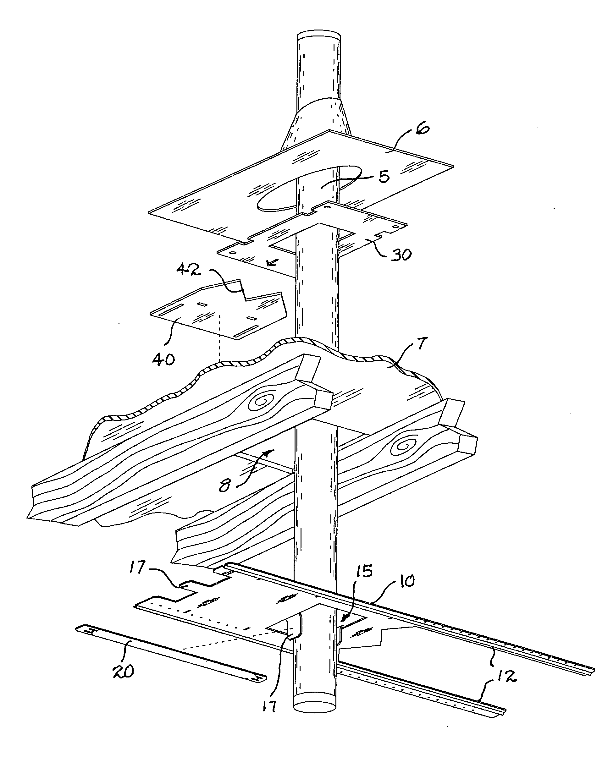
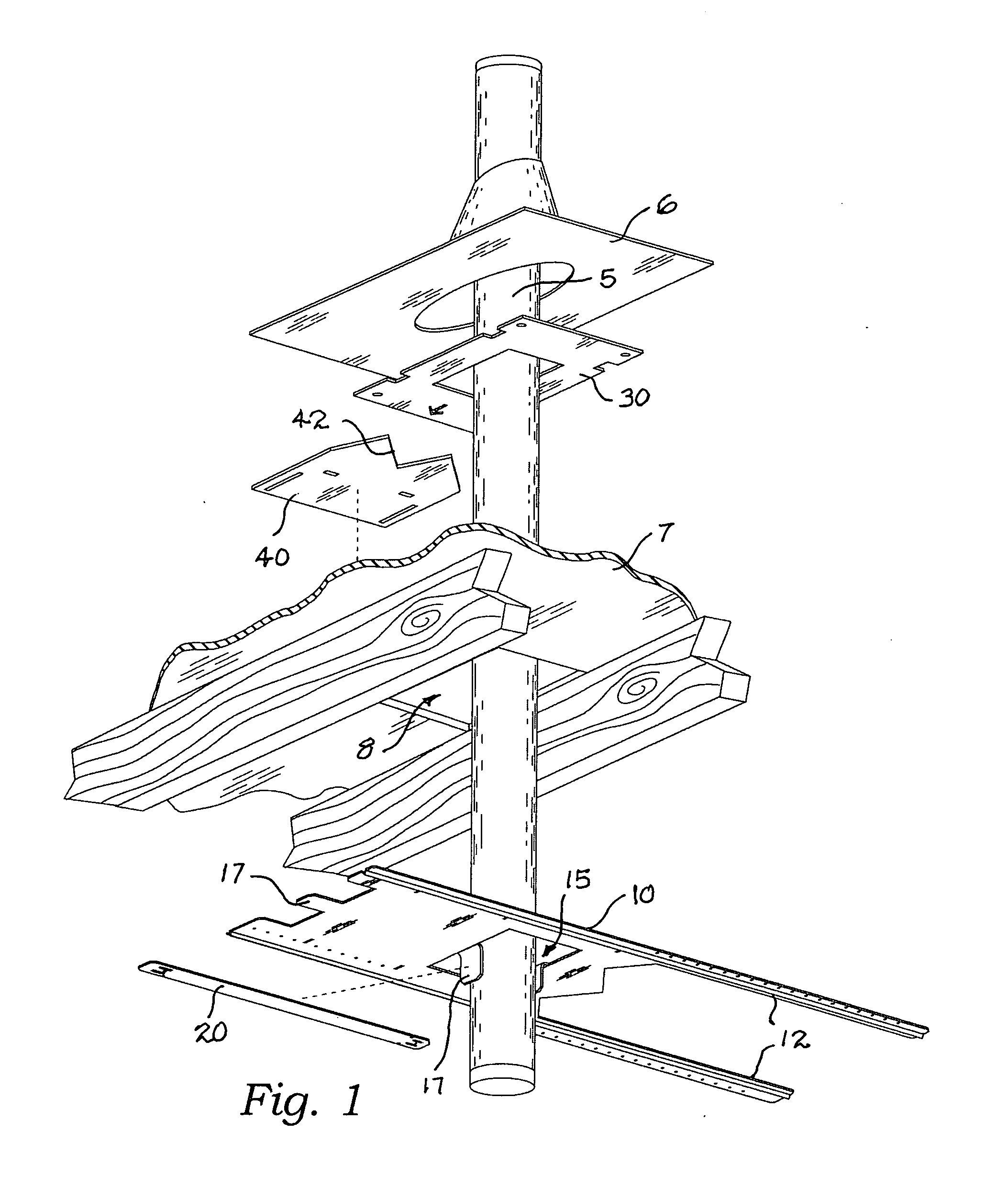
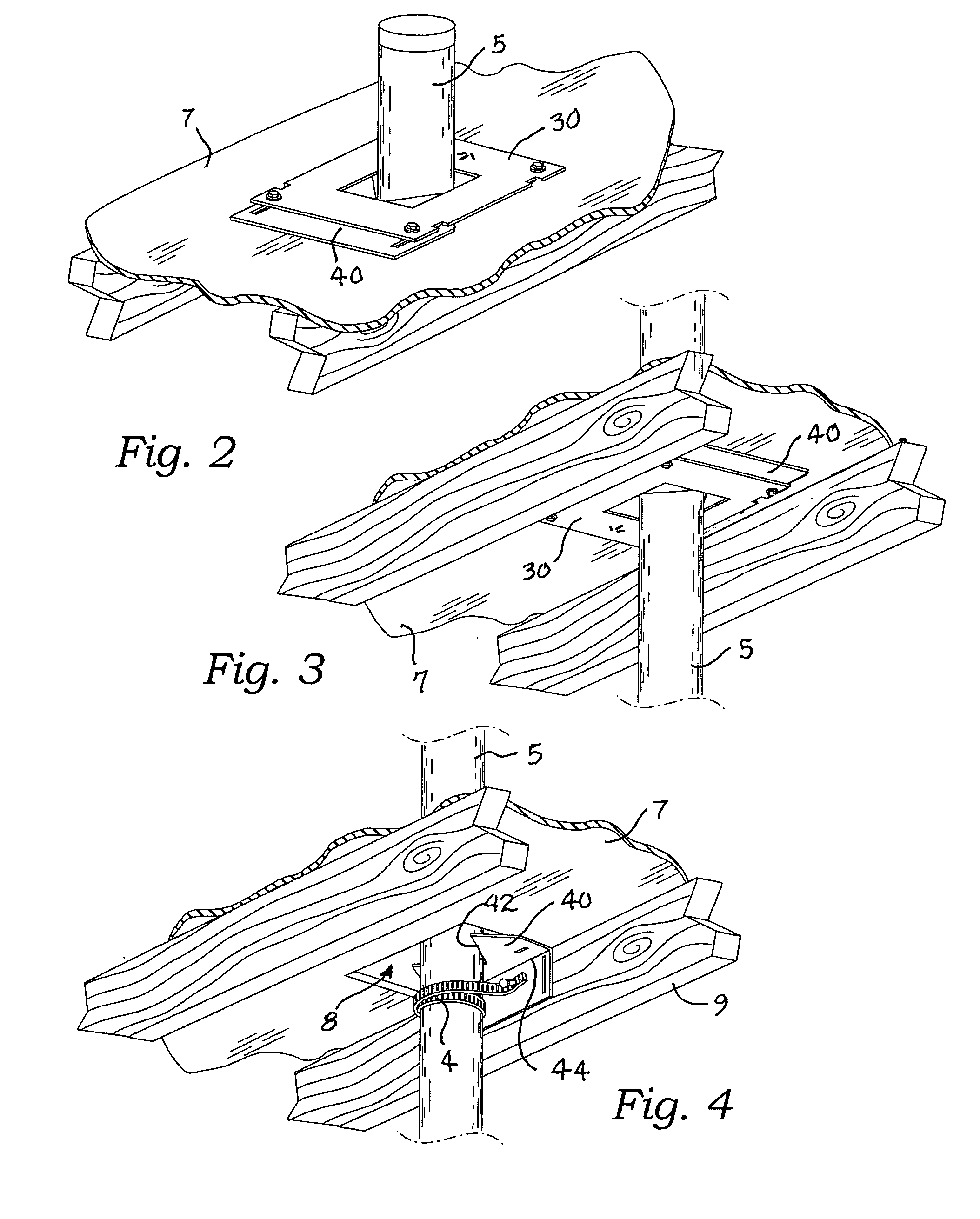
[0026] Described now in detail is an exhaust flue support apparatus, the subject of this application. This apparatus comprises an elongate flue mounting plate 10 defining a longitudinal direction, see arrow “A.” The mounting plate 10 incorporates at least two longitudinal, spaced-apart, strengthening beads 12 (FIGS. 7 and 8) which may be V-shaped or semicircular in cross-section. Other shapes are possible as well. The purpose of these beads 12 is to prevent lateral bending of the mounting plate 10, which is necessary for it to perform its function. The mounting plate 10 is engaged by break-off tabs 14 with a securing strap 20, a centering plate 30, and a butting plate 40 and these four parts: 10, 20, 30 and 40 are arranged in planar juxtaposition as shown in FIGS. 5 and 6. These four parts 10, 20, 30 and 40 are preferably made from a single flat piece of 24 gauge galvanized steel sheet metal and are preferably fabricated at the same time through punching and bending operations well ...

second embodiment

[0027] The mounting plate 10 provides plural mounting holes 16 which are preferably arranged in longitudinal rows as shown, and preferably the rows are placed adjacent to and in line with the opposing lateral edges 18 of the mounting plate 10. The mounting plate 10 also provides a first flue access hole 15 with one or more contiguous strapping-tabs 17 extending into the area defined by the flue access hole 15. Preferably, in one embodiment shown in FIG. 5, the strapping-tabs are aligned longitudinally. In a second embodiment, shown in FIG. 6, the strapping-tabs 17 are oriented at an acute angle to the longitudinal direction. In this embodiment, the tabs 17 are preferably set in pairs and form a V-shape as shown in FIG. 6. Preferably, as shown in FIG. 5, the mounting plate 10 provides a pair of laterally spaced-apart second flue access holes 15′ which are open to an end edge 18′ of the mounting plate 10. In the forming of these holes 15′, preferably by a punching operation, a strappi...


PUM


Abstract

An exhaust flue support apparatus made up of an elongate flue mounting plate defining a first flue access hole with at least one contiguous strapping-tab extending into the flue access hole, the mounting plate incorporating at least two longitudinal, spaced-apart, strengthening beads; a securing strap having a length capable of inscribing the first flue access hole; a centering plate providing an elongated flue access hole; and a butting plate having a V-shaped edge, the securing strap, centering plate and butting plate formed from a single sheet of metal with tabs for easily breaking the securing strap, centering plate and butting plate away from the mounting plate.

Description

CROSS-REFERENCE TO RELATED APPLICATIONS [0001] Not applicable. STATEMENT REGARDING FEDERALLY SPONSORED RESEARCH OR DEVELOPMENT [0002] Not applicable. THE NAMES OF THE PARTIES TO A JOINT RESEARCH AGREEMENT [0003] Not applicable. INCORPORATION-BY-REFERENCE OF MATERIAL SUBMITTED ON A COMPACT DISC [0004] Not applicable. REFERENCE TO A “MICROFICHE APPENDIX”[0005] Not applicable. BACKGROUND OF THE INVENTION [0006] 1. Field of the Present Disclosure [0007] This disclosure relates generally to the support and physical centering of furnace and other exhaust flue pipes and vents and more particularly to an apparatus capable of providing a plurality of connected but easily broken apart sheet metal portions for completing the job. [0008] 2. Description of Related Art Including Information Disclosed Under 37 CFR 1.97 and 1.98 [0009] Reynoso, U.S. Pat. No. Des 257,947 discloses a design for a bracket for mounting a heater vent pipe between joists and rafters. Williamson, U.S. Pat. No. 851,720 dis...

Claims


Application Information

Patent Timeline
Patent Type & Authority Applications(United States)
IPC IPC(8): F23J13/00
CPCF23J13/00
Inventor KOPP, JOHN G.
Owner KOPP JOHN G
Why Eureka
Try Eureka