Check patentability & draft patents in minutes with Patsnap Eureka AI!

Write velocity identification

a technology of velocity identification and write speed, applied in the field of data storage systems, can solve the problems of increasing the difficulty of detection, difficult to appropriately optimize the system, and the difficulty of determining the precise way

Active Publication Date: 2006-10-31
STORAGE TECHNOLOGY CORPORATION
View PDF20 Cites 0 Cited by
  • Summary
  • Abstract
  • Description
  • Claims
  • Application Information

AI Technical Summary

Benefits of technology

This approach enables accurate identification of the write velocity, allowing for optimized equalization adjustments, thereby improving data storage reliability and areal density by compensating for channel transfer function variations, enhancing the performance of tape drives.

Problems solved by technology

As data areal density increases, the peaks get smaller and smaller relative to the background noise, and accordingly, get more and more difficult to detect.
A problem is the fact that it is difficult to appropriately optimize the system because it is difficult to determine the precise way that the equalization needs to be changed.

Method used


Image

  • Write velocity identification
  • Write velocity identification
  • Write velocity identification

Examples


Embodiment Construction

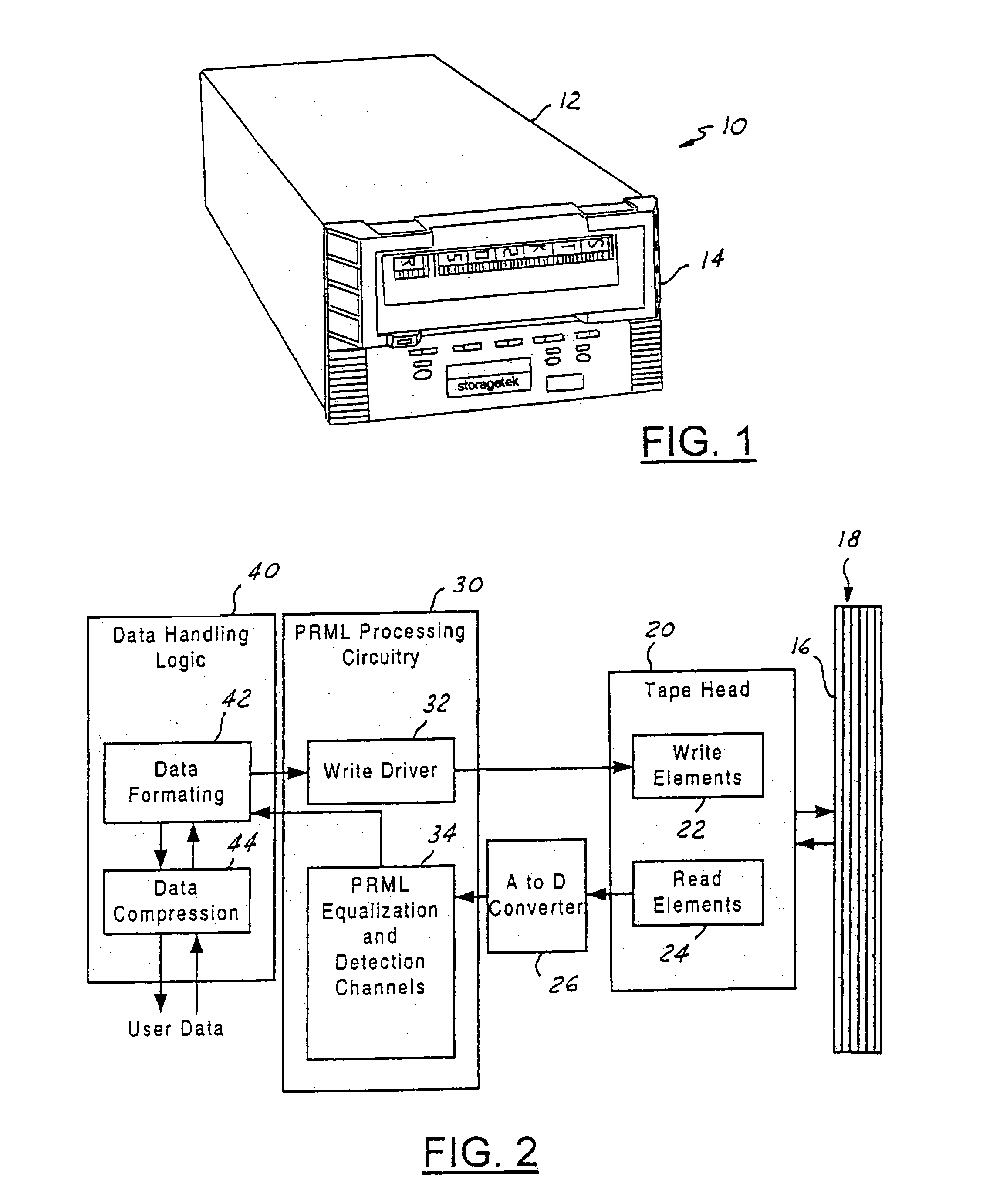
[0020]With reference to FIG. 1, a tape drive is generally indicated at 10. Tape drive 10 includes a housing 12. Housing 12 is for receiving a magnetic tape cartridge 14. Magnetic tape cartridge 14 has multiple parallel tracks. The way that tape drive 10 reads and writes user data is best shown in FIG. 2.

[0021]In FIG. 2, media 16 which is contained within magnetic tape cartridge 14 includes multiple parallel tracks 18. The number of parallel tracks that are simultaneously readable / writeable will vary depending on the application, as may various aspects of the tape drive 10 and tape cartridge 14. That is, the tape has hundreds of parallel tracks with a handful being written or read at one time in parallel.

[0022]Tape head 20 is for reading and writing the tracks 18 of media 16. Tape head 20 may take any suitable form. Writing is conducted with write elements 22, and reading is conducted with read elements 24. It is further appreciated that the read and write elements may take any suita...


PUM

PropertyMeasurementUnit
transport velocityaaaaaaaaaa
velocityaaaaaaaaaa
transition frequencyaaaaaaaaaa

Abstract

A drive and method of identifying write velocity during reading are provided. When a track is being read, the data signal is processed prior to determining the data stream to identify the velocity with which the track data were written. The read channel is adjusted based on the identified velocity to compensate for write channel transfer function variation.

Description

CROSS-REFERENCE TO RELATED APPLICATIONS[0001]This application is a continuation of U.S. application Ser. No. 10 / 862,586, filed Jun. 7, 2004 now U.S. Pat. No. 6,956,709.BACKGROUND OF THE INVENTION[0002]1. Field of the Invention[0003]The present invention relates to data storage systems.[0004]2. Background Art[0005]In a traditional magnetic storage medium, a read circuit detects flux reversals to determine a data signal. Peak detection is used to interpret the information present in the data signal. As data areal density increases, the peaks get smaller and smaller relative to the background noise, and accordingly, get more and more difficult to detect. A technique used to allow further increases in data areal density that addresses difficulties associated with peak detection is partial response maximum likelihood (PRML).[0006]PRML does not attempt to detect individual peaks in the way that the traditional peak detection techniques do. PRML uses digital signal processing to analyze th...

Claims


Application Information

Patent Timeline
Patent Type & Authority Patents(United States)
IPC IPC(8): G11B5/09G11B15/46G11B5/00G11B5/008G11B20/10G11B27/32G11B27/36
CPCG11B5/00813G11B15/46G11B15/52G11B20/10009G11B20/10055G11B27/328G11B27/36G11B2005/001G11B2020/10981G11B2220/90
Inventor BOYER, KEITH GARYGILL, RICHARD ALLEN
Owner STORAGE TECHNOLOGY CORPORATION
Features
  • R&D
  • Intellectual Property
  • Life Sciences
  • Materials
  • Tech Scout
  • Unparalleled Data Quality
  • Higher Quality Content
  • 60% Fewer Hallucinations
Learn More