Automatic rain gutter flushing system

a rain gutter and automatic technology, applied in the direction of roof drainage, watering devices, cleaning using liquids, etc., can solve the problem of not describing an automatic rain gutter flushing system that allows, and achieve the effects of low manufacturing cost, convenient and efficient manufacturing and marketing, and durable and reliable construction

Inactive Publication Date: 2007-03-13
MULLINS MICHAEL S +1
View PDF9 Cites 13 Cited by
  • Summary
  • Abstract
  • Description
  • Claims
  • Application Information

AI Technical Summary

Benefits of technology

[0020]It is another object of the present invention to provide a new and improved automatic rain gutter flushing system which may be easily and efficiently manufactured and marketed.
[0021]It is a further object of the present invention to provide a new and improved automatic rain gutter flushing system which is of durable and reliable constructions.
[0022]An even further object of the present invention is to provide a new and improved automatic rain gutter flushing system which is susceptible of a low cost of manufacture with regard to both materials and labor, and which accordingly is then susceptible of low prices of sale to the consuming public, thereby making such automatic rain gutter flushing system economically available to the buying public.

Problems solved by technology

While these devices fulfill their respective, particular objectives and requirements, the aforementioned patents do not describe an automatic rain gutter flushing system that allows automatically cleaning and flushing leaves and other debris from gutters and downspouts.

Method used


Image

  • Automatic rain gutter flushing system
  • Automatic rain gutter flushing system
  • Automatic rain gutter flushing system

Examples


Embodiment Construction

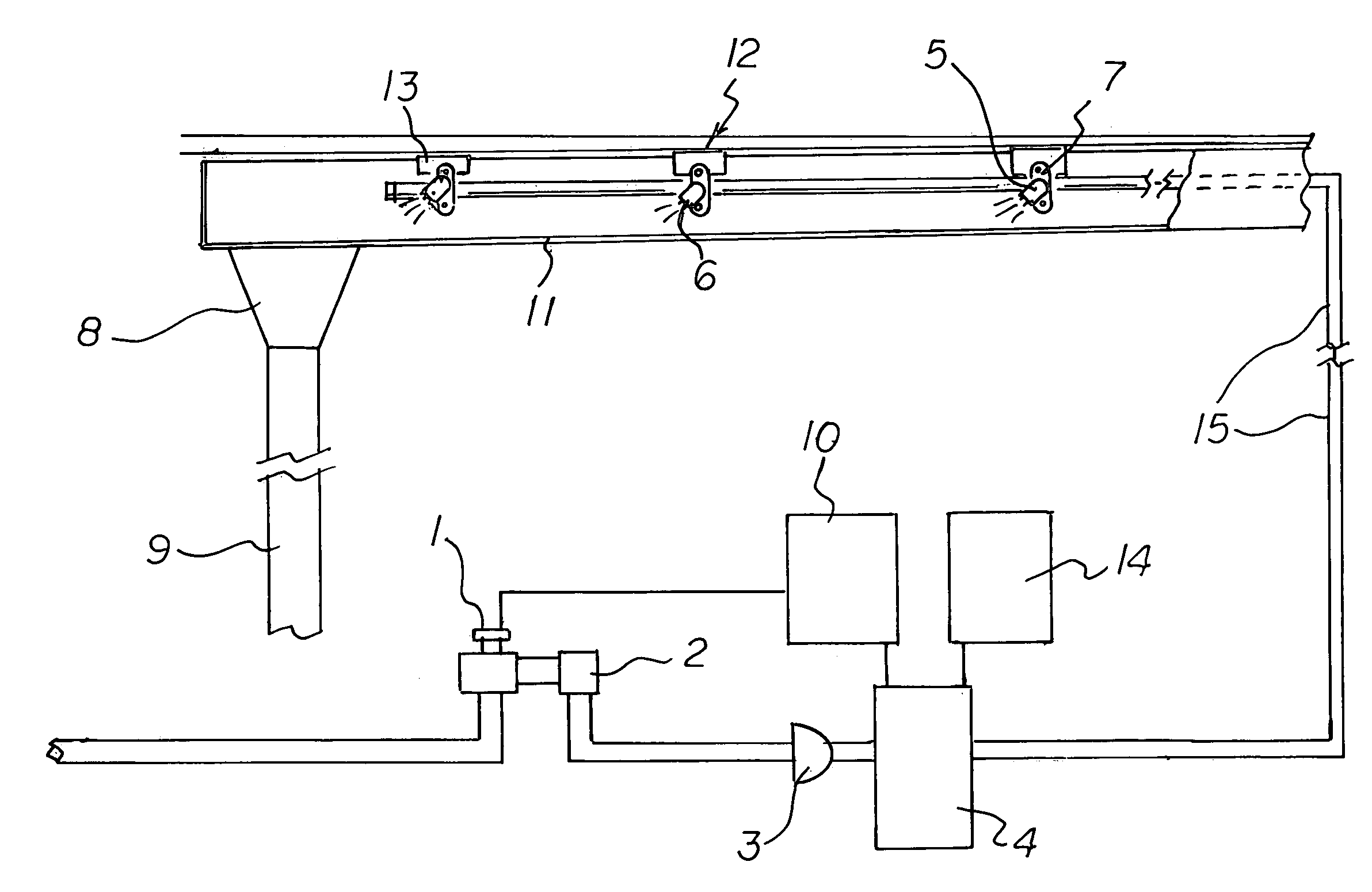
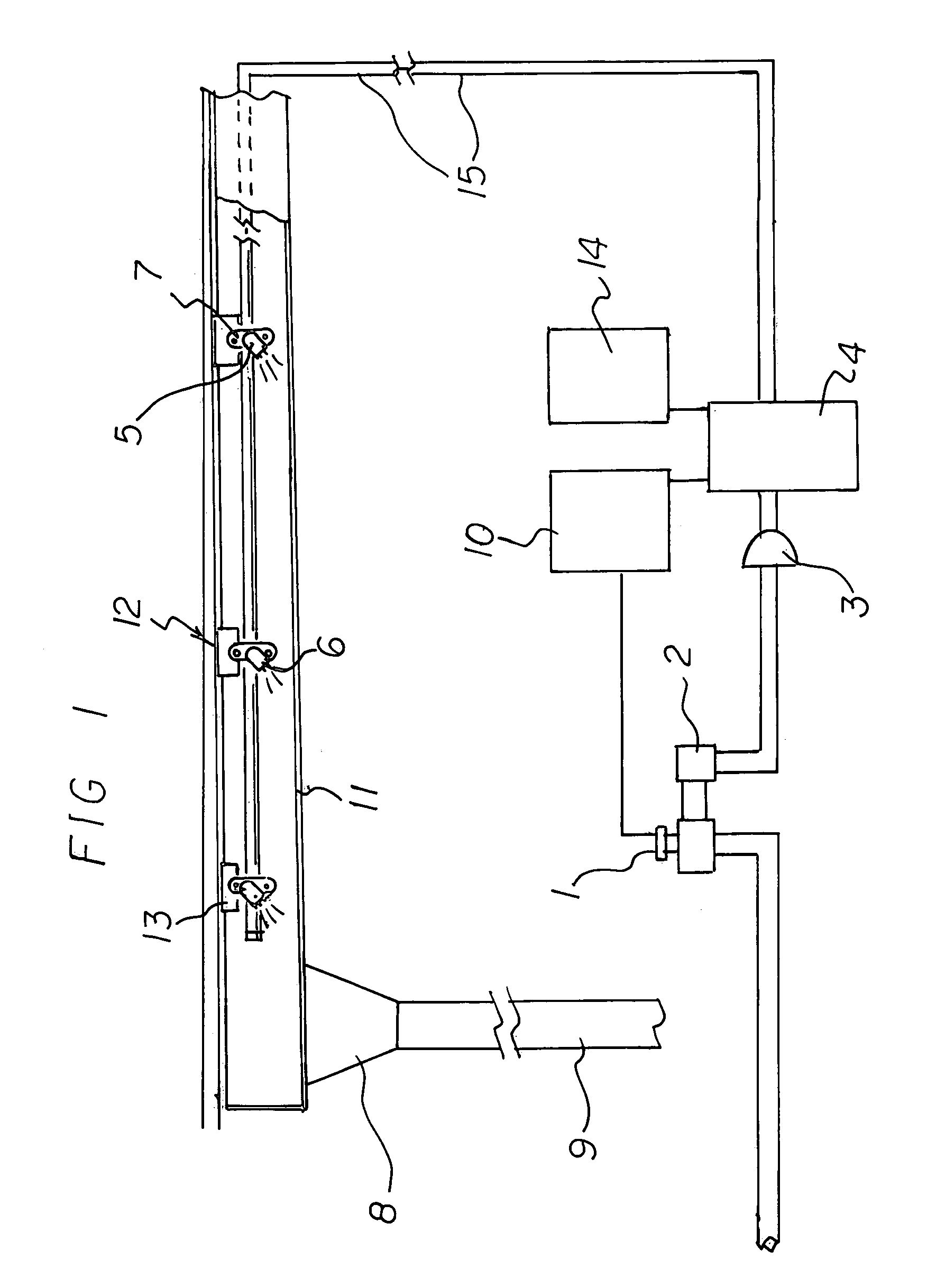
[0033]With reference now to the drawings, and in particular to FIG. 1, thereof, the preferred embodiment of the new and improved automatic rain gutter flushing system embodying the principles and concepts of the present invention will be described.

[0034]The present invention, the automatic rain gutter flushing system is comprised of a plurality of components. Such components in their broadest context include a gutter, a downspout, spraying components, a conduit and control components. Such components are individually configured and correlated with respect to each other so as to attain the desired objective.

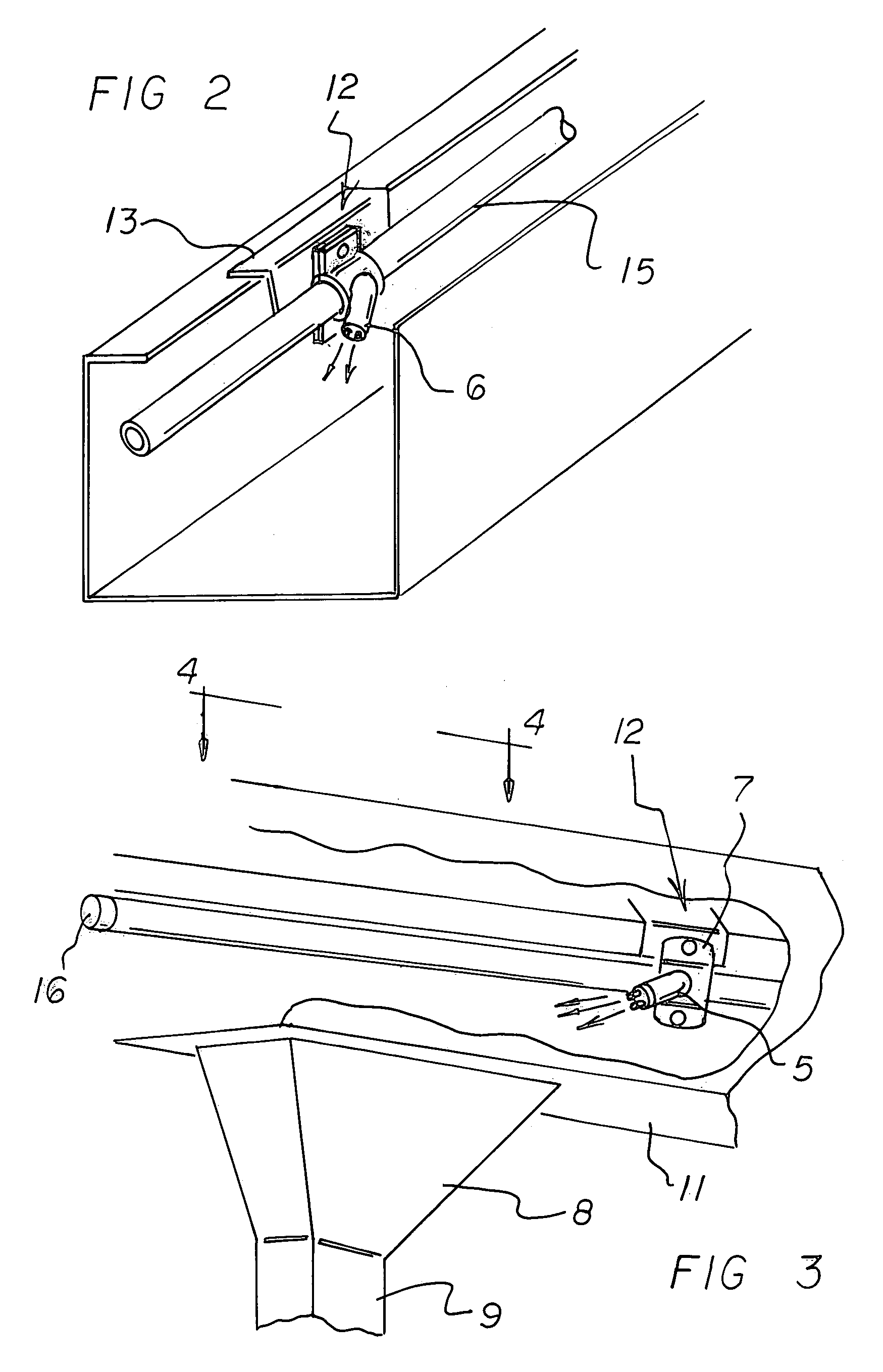
[0035]First provided is an eave gutter 11. The gutter is positionable in proximity to the periphery of a roof of a building. In this manner water, leaves and other debris are directed.

[0036]A standard 3 inch by 4 inch downspout 9 is provided. The downspout has an upper end. The upper end is coupled with respect to the gutter. The downspout has a lower end. The lower end directs wa...


PUM


Abstract

An eave gutter is provided. A downspout is operatively coupled to the gutter. A plurality of spraying components has fittings and nozzles. The fittings and nozzles are positioned at spaced locations along the gutter. A conduit couples a fluid source and the fittings and nozzles to provided fluid to the gutter. Control components are provided along the conduit to the fittings and nozzles.

Description

RELATED APPLICATION[0001]The present application is based upon U.S. Provisional Application Ser. No. 60 / 588,637 filed Jul. 17, 2004.BACKGROUND OF THE INVENTION[0002]1. Field of the Invention[0003]The present invention relates to an automatic rain gutter flushing system and more particularly pertains to automatically cleaning and flushing leaves and other debris from gutters and downspouts.[0004]2. Description of the Prior Art[0005]The use of gutter systems of known designs and configurations is known in the prior art. More specifically, gutter systems of known designs and configurations previously devised and utilized for the purpose of removing debris from gutters through known methods and configurations are known to consist basically of familiar, expected, and obvious structural configurations, notwithstanding the myriad of designs encompassed by the crowded prior art which has been developed for the fulfillment of countless objectives and requirements.[0006]While these devices fu...

Claims


Application Information

Patent Timeline
Patent Type & Authority Patents(United States)
IPC IPC(8): B05B3/00
CPCB05B12/04E04D13/0765B05B1/202Y10S239/15B05B15/069B05B15/658
Inventor MULLINS, MICHAEL S.MULLINS, PHYLLIS J.
Owner MULLINS MICHAEL S
Why Eureka
Try Eureka