Solid-liquid separator

a technology of solid-liquid separator and separator chamber, which is applied in the direction of sedimentation settling tank, separation process, centrifuge, etc., can solve the problems of reduced fluidity, easy clogging of tubular body interior, so as to prevent clogging caused by material being treated and achieve efficient separation of material being treated

Inactive Publication Date: 2007-03-20
AMUKON
View PDF11 Cites 15 Cited by
  • Summary
  • Abstract
  • Description
  • Claims
  • Application Information

AI Technical Summary

Benefits of technology

[0005]The object of the present invention is to provide a solid-liquid separator that can eliminate, or else effectively minimize, the above-described drawbacks to the conventional art.
[0010]In accordance with the present invention, clogging caused by the material being treated can be prevented, and solid-liquid separation of the material being treated can be performed efficiently.

Problems solved by technology

However, with such a conventional solid-liquid separator, when a material that can easily lose its fluidity is subject to dewatering, such material, having undergone liquid separation within a tubular body, has reduced fluidity, and adheres to the surface of the screw and begins to rotate unitarily with the screw.
If this happens, the material is not transported by the screw, and there is the danger that the tubular body interior will become clogged.
Particularly in the case of inorganic sludge and chopped vegetables scraps, fruit rinds, or bran and foodstuff remains, the tubular body interior can easily become clogged.

Method used


Image

  • Solid-liquid separator
  • Solid-liquid separator
  • Solid-liquid separator

Examples


Embodiment Construction

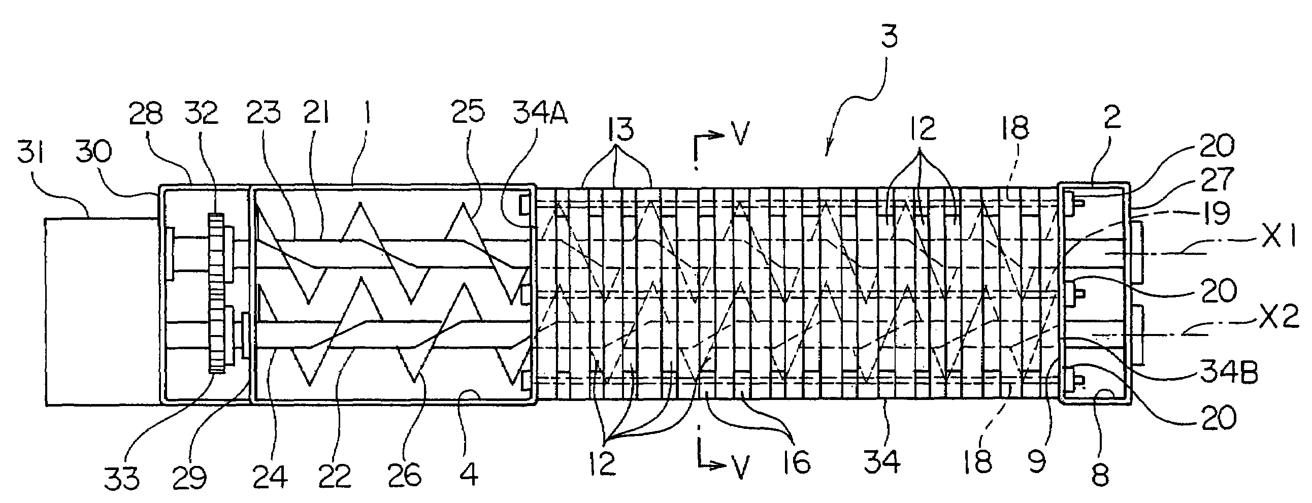
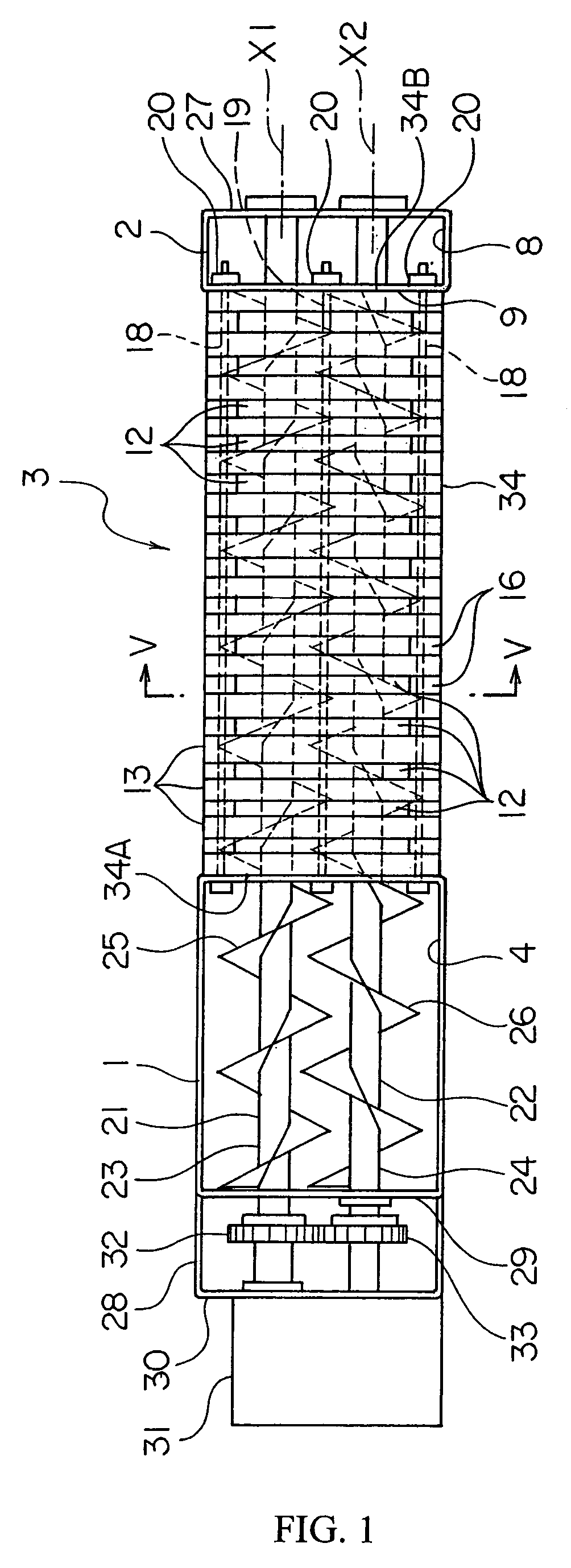
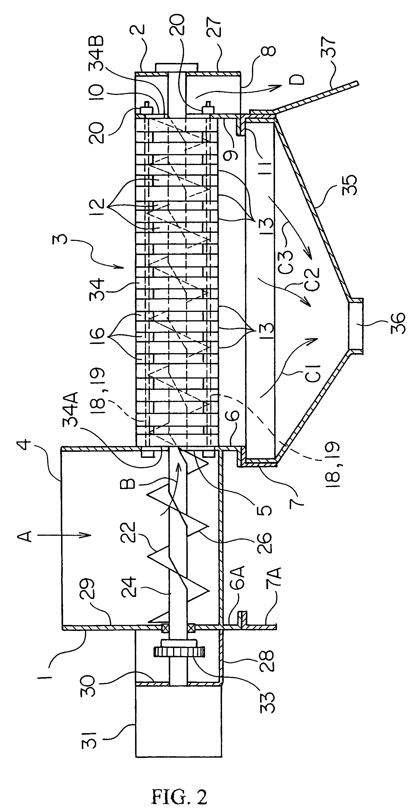
[0028]FIG. 1 is a plan view showing a solid-liquid separator, and FIG. 2 is a partial cross-sectional frontal view of that solid-liquid separator. With such a solid-liquid separator, any of the materials for treatment described above as well as other material can undergo solid-liquid separation; here, an explanation will be given for the dewatering of sludge containing a large volume of water.

[0029]The solid-liquid separator showed herein comprises an inlet member 1 and an outlet member 2, and a solid-liquid separator unit 3 is disposed between this inlet member 1 and outlet member 2. The inlet member 1 is formed with a box shape and at the top thereof is formed an inflow opening 4 into which sludge flows; further, an opening 5 is formed on a portion of the inlet member 1 facing the solid-liquid separator unit 3. Lower flanges 6, 6A, which continue from the bottom wall of the inlet member 1, are fixed to stays 7, 7A on the device frame. The outlet member 2 has a horizontal cross-sec...


PUM

PropertyMeasurementUnit
thicknessaaaaaaaaaa
thicknessaaaaaaaaaa
thicknessaaaaaaaaaa

Abstract

A system is provided with a solid-liquid separator which can transport sludge and other material for treatment without clogging and can efficiently separator liquid from such material for treatment. The system includes movable plates and fixed plates alternatingly disposed and two screws disposed in holes formed in the movable plates and fixed plates. The screws have blades that partially overlap. As the two screws rotate, the material for treatment is transported and the effluent is discharged through the gaps between the movable plates and fixed plates.

Description

BACKGROUND OF THE INVENTION[0001]The present invention relates to a solid-liquid separator for separating liquid from a material for treatment that contains a large volume of liquid.[0002]Solid-liquid separators that separate liquid from a material for treatment containing a large volume of liquid are commonly known and described in, for example, JP 7-10440. Material treated by such a solid-liquid separator include, for example, organic sludge such as wastewater from food processing, sewage, or wastewater from pig farms; inorganic sludge such as cutting lubricant containing chips, waste fluid from plating, ink waste fluid, pigment waste fluid and paint waste fluid; or else chopped vegetable scraps and fruit skins, bran, and foodstuff remains.[0003]A conventional solid-liquid separator has a screw that extends through a tubular body, material for treatment that has flowed into the tubular body from an inlet opening on one end in the axial direction of the tubular body is transported ...

Claims


Application Information

Patent Timeline
Patent Type & Authority Patents(United States)
IPC IPC(8): B30B9/16B01D35/00B01D33/04B01D29/25B01D29/82B01D33/00B01D43/00B30B9/06B30B9/14C02F11/12E03F5/14
CPCB30B9/26B30B9/16C02F11/125B04B1/20C02F2201/002Y02W10/20
Inventor SASAKI, MASAYOSHI
Owner AMUKON
Why Eureka
Try Eureka