Low-Noise Rotor Chamber For A Centrifuge

Active Publication Date: 2010-07-15
QIAGEN
View PDF15 Cites 4 Cited by
  • Summary
  • Abstract
  • Description
  • Claims
  • Application Information

AI Technical Summary

Benefits of technology

[0027]The effects of the molded part supplement the effects of the damping lining particularly favorably if the rotor chamber is seated in the molded part so that the molded part and the damping lining are free of overlap in the axial direction. Molded part and damping lining thus merge into one another nearly continuously and therefore have hardly any gaps in their entirety, via which undamped emission of sound waves from the rotor chamber is possible.
[0028]Finally, a further aspect of the present invention is a method for reducing the sound emanating from the rotor chamber of a centrifuge, in particular an air-cooled laboratory centrifuge, comprising the combination of the following steps: a) absorbing the sound using a first layer and b) reflecting the sound using a second layer. The basic concept of the invention is thus expanding the damping lining in its property spectrum so that it comprises both sound-absorbing and also sound-reflecting properties. For this purpose, at least one first layer and one second layer are com

Problems solved by technology

The rotor chamber is ultimately used for receiving the centrifuge rotor rotating therein and is therefore particularly susceptible to the pressure waves cau

Method used


Image

  • Low-Noise Rotor Chamber For A Centrifuge
  • Low-Noise Rotor Chamber For A Centrifuge

Examples


Example

[0035]Referring now to the figures, identifical components are provided with identical reference numerals in the embodiments shown hereafter.

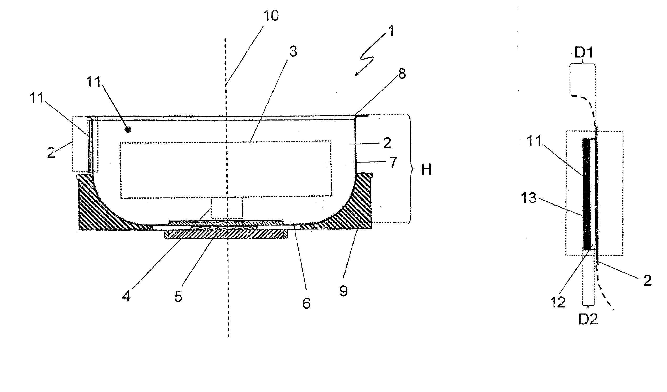
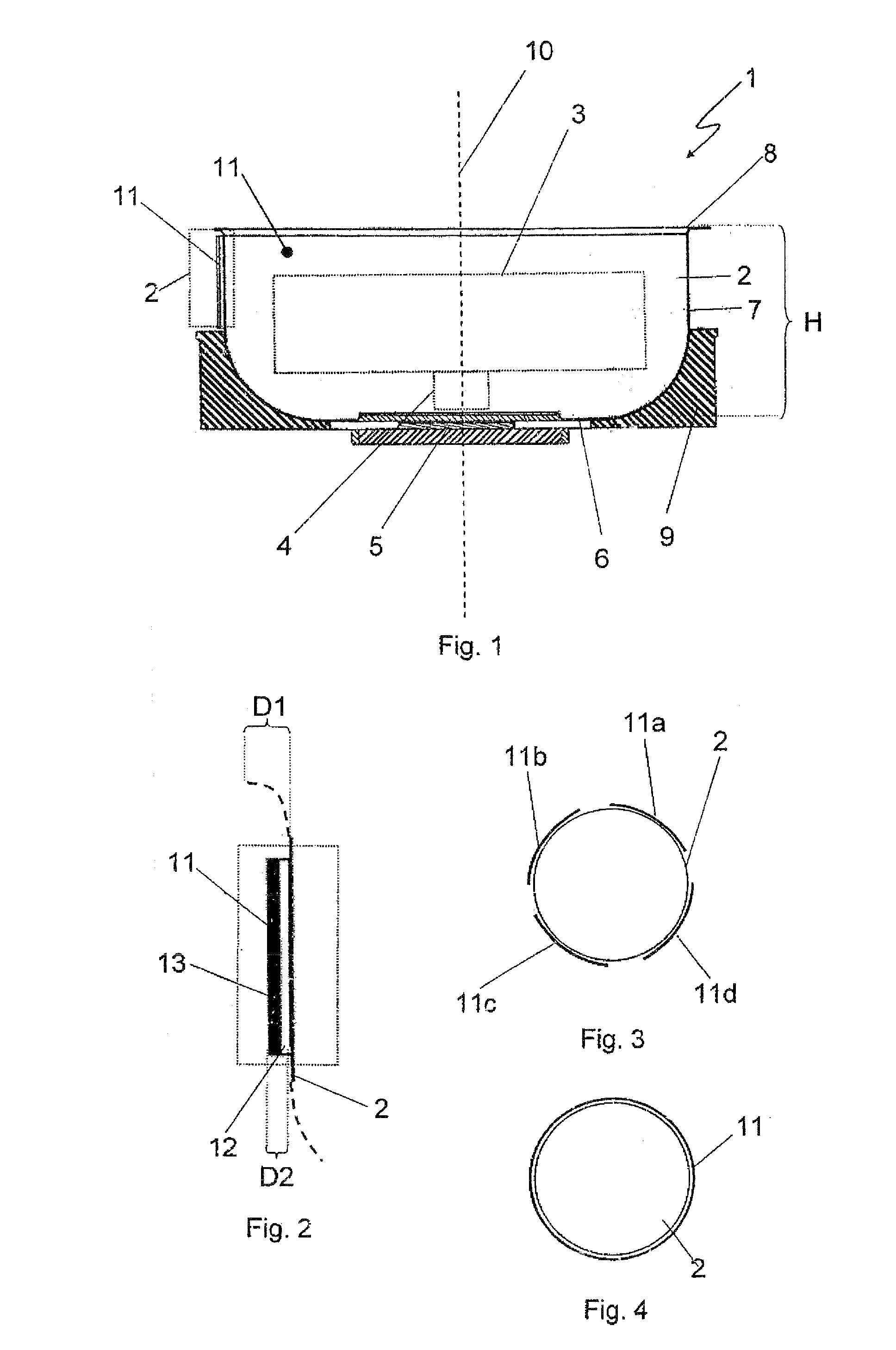
[0036]The centrifuge 1, which is only partially shown in FIG. 1, comprises a rotor chamber 2 in a housing (not shown) for receiving a rotor 3 indicated by dashed lines (in particular a swing-out rotor), which is connected via a drive shaft 4 to a motor element 5. The rotor chamber 2 also comprises a flat base area 6, a wall area 7 adjoining thereon on top, and an upper edge area 8. The rotor chamber 2 is implemented as open on top and is covered to the outside in operation by a lid (not shown). Furthermore, in its lower area the rotor chamber 2 is received in a foam molded part 9 implemented as trough-like, which extends from the base area 6 up to approximately half the height H of the rotor chamber 2. A damping lining 11 adjoins the foam molded part 9 on top in the direction of the rotational axis 10, around which the rotor 3 rotates in operat...


PUM

PropertyMeasurementUnit
Timeaaaaaaaaaa
Thicknessaaaaaaaaaa
Thicknessaaaaaaaaaa

Abstract

The present invention relates to a rotor chamber for a centrifuge, in particular an air-cooled laboratory centrifuge, having a chamber wall, comprising an inner side facing toward the chamber interior, the chamber interior being implemented to receive a centrifuge rotor, and an outer side facing away from the chamber interior, and having a sound barrier which is implemented to reduce the sound emitted from the rotor chamber, which comprises a multilayer damping lining. The present invention also relates to a centrifuge having such a rotor chamber, and methods for reducing the sound emanating from the rotor chamber of a centrifuge, in particular an air-cooled laboratory centrifuge.

Description

RELATED APPLICATION[0001]The present application claims the priority under 35 U.S.C. §119 of German Patent Application No. 102009004748.4, filed Jan. 15, 2009, the disclosure of which is hereby incorporated herein by reference in its entirety.FIELD OF THE INVENTION[0002]The present invention relates to a rotor chamber for a centrifuge, in particular for an air-cooled laboratory centrifuge, having a chamber wall, comprising an inner side facing toward the chamber interior, the chamber interior being implemented to receive a centrifuge rotor, and an outer side facing away from the chamber interior, and having a sound barrier, which is implemented to reduce the sound emitted by the rotor chamber. Furthermore, the present invention relates to a centrifuge having such a rotor chamber, and a method for reducing the sound emanating from a rotor chamber of a centrifuge, in particular an air-cooled laboratory centrifuge.BACKGROUND OF THE INVENTION[0003]Centrifuges, in particular air-cooled l...

Claims


Application Information

Patent Timeline
IPC IPC(8): B04B7/02B04B15/02
CPCB04B7/02B04B15/02
Inventor JANZEN, HANS
Owner QIAGEN
Why Eureka
Try Eureka