Exhaust systems and methods for gas turbine engine

Active Publication Date: 2018-12-06
HONEYWELL INT INC
View PDF0 Cites 0 Cited by
  • Summary
  • Abstract
  • Description
  • Claims
  • Application Information

AI Technical Summary

Benefits of technology

[0006]Further provided is a method for attenuating sound generated by a gas turbine engine with an exhaust system. The method includes: receiving a primary exhaust fluid in a primary manifold; receiving a secondary cooling fluid in a secondary plenum; directing the primary exhaust fluid through a plurality of eductor primary flow paths associated

Problems solved by technology

In these instances, noise generated by the auxiliary power unit may be undesirable t

Method used


Image

  • Exhaust systems and methods for gas turbine engine
  • Exhaust systems and methods for gas turbine engine
  • Exhaust systems and methods for gas turbine engine

Examples


Embodiment Construction

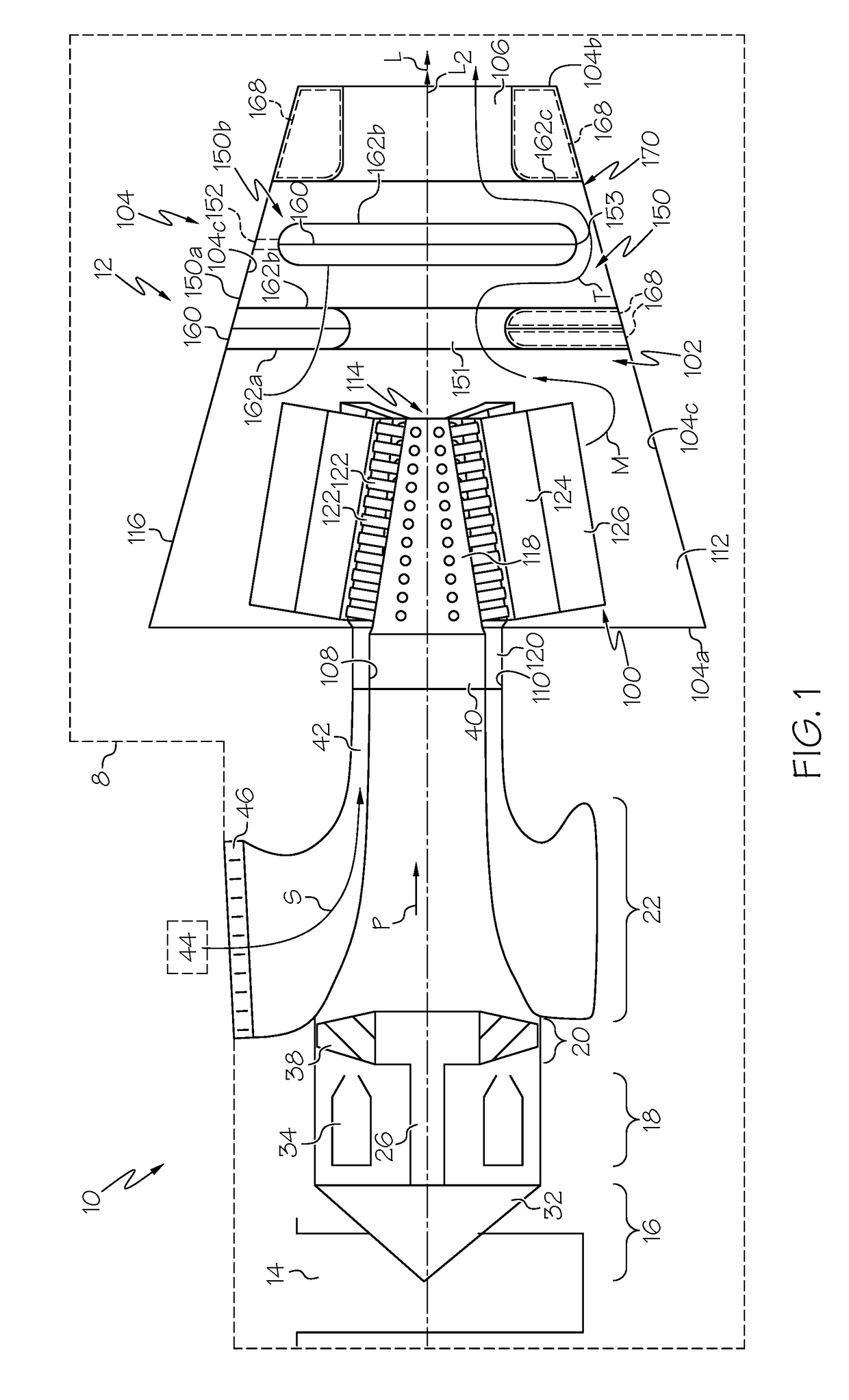
[0015]The following detailed description is merely exemplary in nature and is not intended to limit the application and uses. Furthermore, there is no intention to be bound by any expressed or implied theory presented in the preceding technical field, background, brief summary or the following detailed description. In addition, those skilled in the art will appreciate that embodiments of the present disclosure may be practiced in conjunction with any type of gas turbine engine that would benefit from an exhaust system and method that attenuates the sound generated by the gas turbine engine, and that the gas turbine engine described herein as an auxiliary power unit is merely one exemplary embodiment according to the present disclosure. Moreover, while the exhaust system and method is described herein as being used with a gas turbine engine onboard a mobile platform or vehicle, such as a bus, motorcycle, train, motor vehicle, marine vessel, aircraft, rotorcraft and the like, the vari...


PUM


Abstract

Systems and methods for an exhaust system for a gas turbine engine are provided. The method includes: receiving a primary exhaust fluid in a primary manifold; receiving a secondary cooling fluid in a secondary plenum; directing the primary exhaust fluid through a plurality of eductor primary flow paths associated with a respective plurality of ducts spaced circumferentially about a primary manifold, the plurality of eductor primary flow paths extending through the secondary plenum; and mixing the primary exhaust fluid and the secondary cooling fluid in a mixing chamber associated with a respective one of the plurality of ducts to create a mixed fluid flow.

Description

CROSS-REFERENCE TO RELATED APPLICATION[0001]This application is a divisional of U.S. patent application Ser. No. 15 / 161,581 filed on May 23, 2016. The relevant disclosure of the above application is incorporated herein by reference.TECHNICAL FIELD[0002]The present disclosure generally relates to gas turbine engines, and more particularly relates to an exhaust system and method for a gas turbine engine.BACKGROUND[0003]Gas turbine engines may be employed to power various devices. For example, a gas turbine engine may be employed to supply power to a mobile platform, such as an aircraft. In certain examples, the gas turbine engine is an auxiliary power unit, which can supply power to run various electrical systems of the aircraft. Certain electrical systems are supplied by a generator, through a gearbox driven by the gas turbine engine. As needs for power increase, heat output by the generator into a compartment of the gas turbine engine may increase and a temperature of the lubricatin...

Claims


Application Information

Patent Timeline
IPC IPC(8): F01N1/08F02K1/38F01D25/30F02C7/14F01N3/05
CPCF02K1/386F01D25/30F01N1/083F02C7/14F01N3/05F05D2220/32
Inventor SHIN, YOONSHIKSHEORAN, YOGENDRA YOGIBROWN, DANIEL
Owner HONEYWELL INT INC
Why Eureka
Try Eureka