Heat exchanger

Inactive Publication Date: 2006-03-07
SHOWA DENKO KK
View PDF14 Cites 10 Cited by
  • Summary
  • Abstract
  • Description
  • Claims
  • Application Information

AI Technical Summary

Benefits of technology

[0020]With the evaporator according to the fourth feature of the invention, the fluid inlet pipe socket is positioned below the fluid outlet pipe socket. This makes it possible to reduce the front-to-rear width of the pipe connecting member with a reduction in the width of the evaporator body. Each communication passageway in the plate member is inclined, and the angle of inflow or outflow between the passageway within the block member and this communication channel and the angle of inflow or outflow between the communication channel and the header are each an obtuse angle. This serves to attenuate the striking contact of the fluid with the corner portions, decreasing the resistance to the flow and reducing the sound produced by the flow of fluid for the diminution of noise. Also overcome is the problem that a large amount of fluid will fall at the inlet of the front header to impair uniform distribution of the fluid to the flat tubes.
[0021]With t

Problems solved by technology

Furthermore, the presence of the corner portion having a curved surface attenuates the striking contact of the fluid with the corner portion, decreasing the resistance to the flow and reducing the sound produced

Method used


Image

  • Heat exchanger
  • Heat exchanger
  • Heat exchanger

Examples


Example

BEST MODE OF CARRYING OUT THE INVENTION

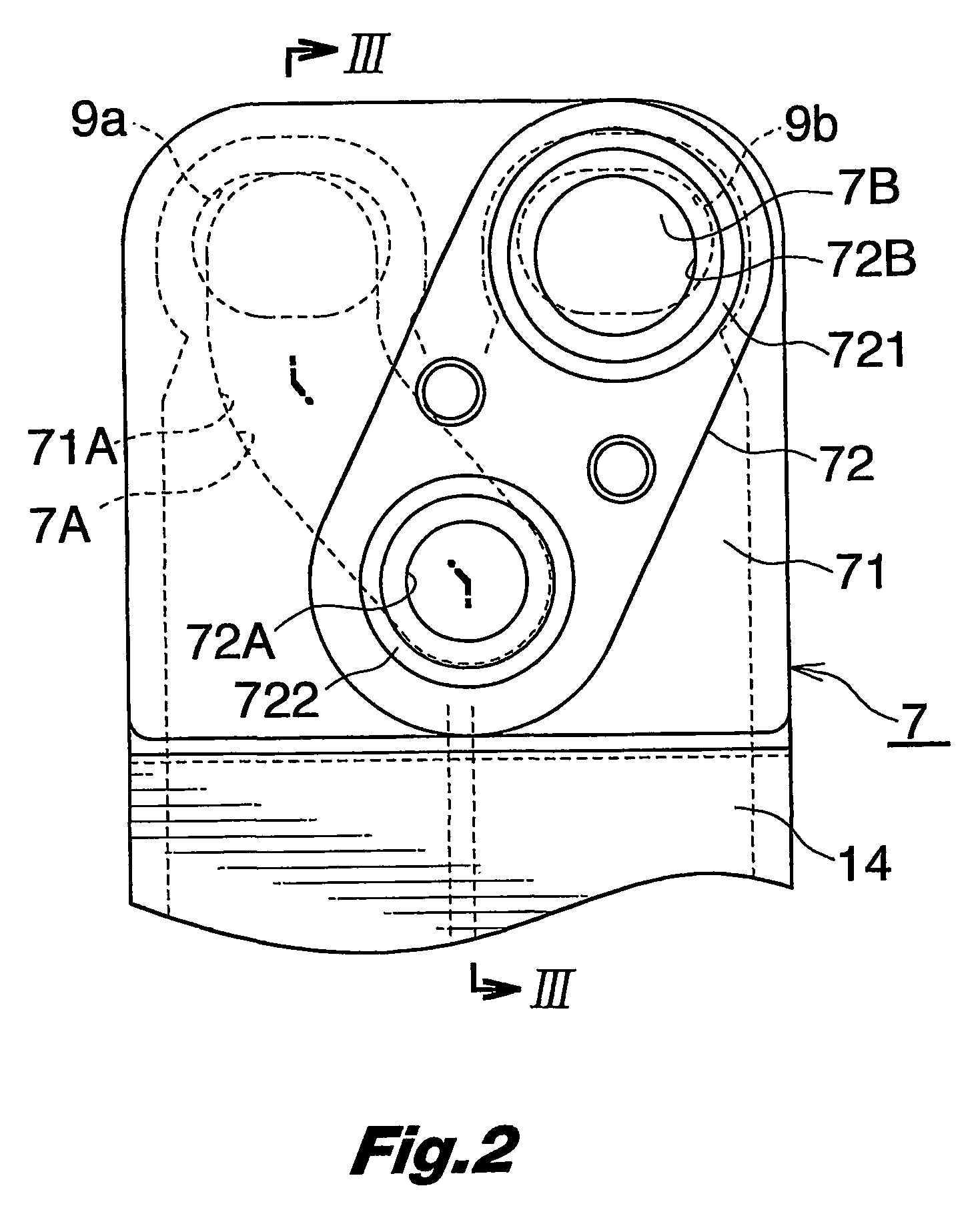
[0028]An embodiment of the invention according to a first feature thereof will be described with reference to FIGS. 1 to 3.

[0029]In the following description, the term “front” refers to the left-hand side of FIG. 2, the term “rear” to the right-hand side of the drawing, and the terms “left” and “right” are used for the heat exchanger as it is seen from the front rearward.

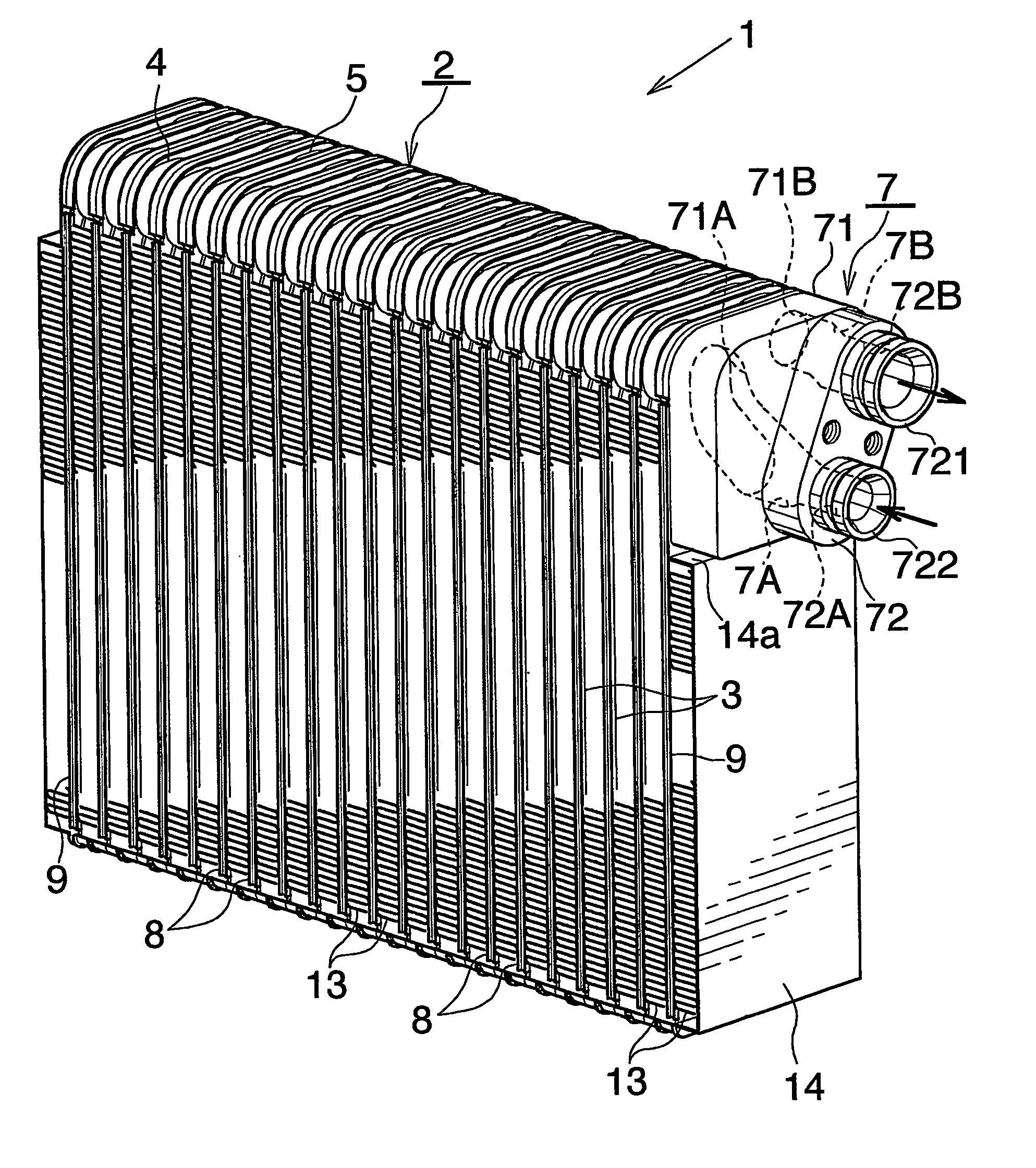
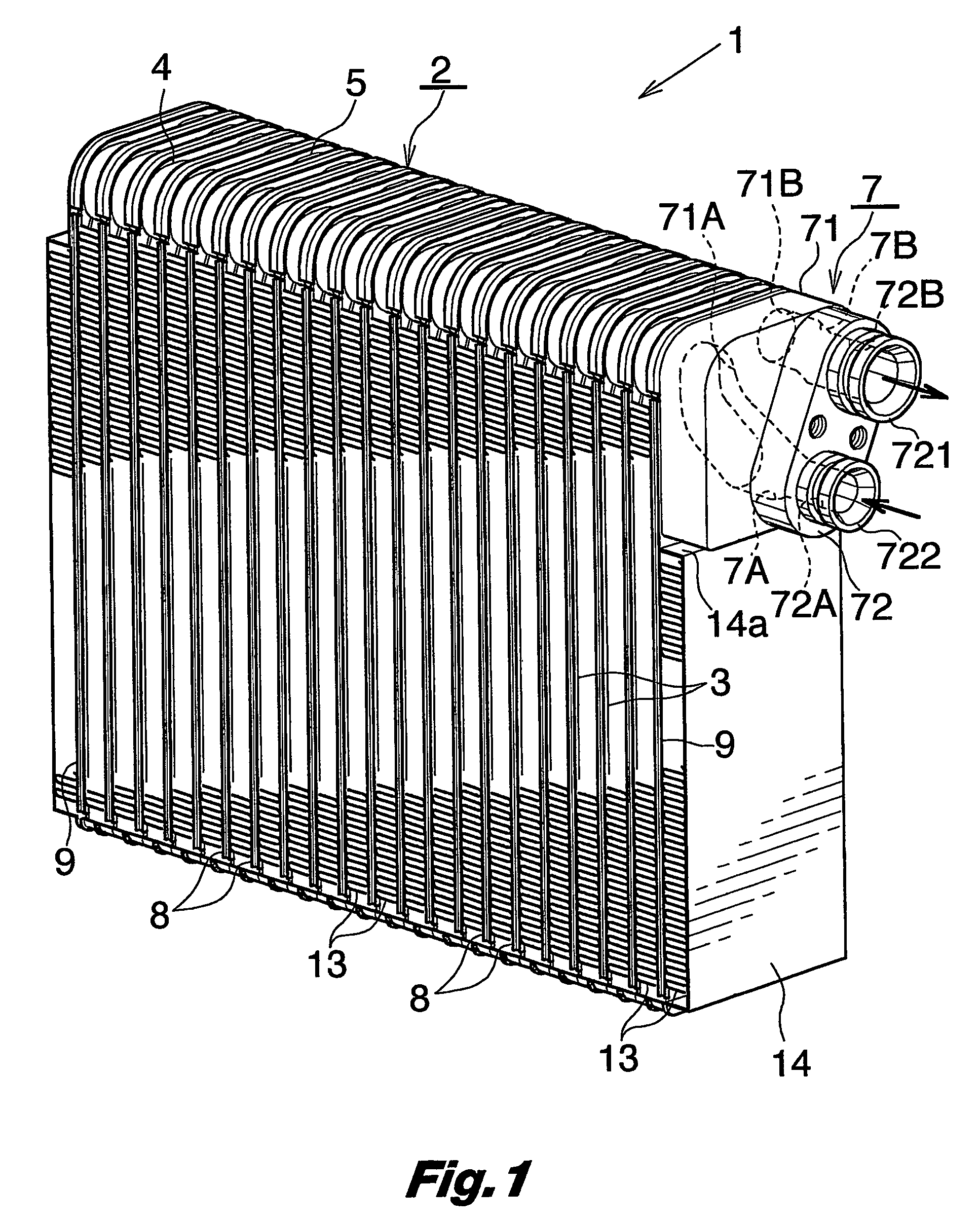
[0030]These drawings show a heat exchanger 1 for use as an evaporator for motor vehicle air conditioners. The exchanger has a heat exchanger body 2 comprising a plurality of vertical flat tubes 3 arranged laterally at a predetermined spacing and each having a front and a rear fluid channel, a front header 4 extending from left to right, interconnecting the upper ends of the front fluid channels of all the flat tubes 3 and each having an open right end and a closed left end, and a rear header 5 extending from left to right, interconnecting the upper ends of the rear fluid channe...


PUM


Abstract

A pipe connecting member 7 has a fluid outlet passage 7B formed in communication with a fluid outlet pipe socket 721 provided thereon at a position on a lateral extension of the fluid outlet hole 9b, and a fluid inlet passage 7A formed with a fluid inlet pipe socket 722 provided thereon as displaced from a position on a lateral extension of the fluid inlet hole 7a. A corner portion 95 having a curved surface is formed between the fluid inlet passage 7A and a front header 4.

Description

CROSS REFERENCE TO RELATED APPLICATIONS[0001]This application is an application filed under 35 U.S.C. §111(a) claiming the benefit pursuant to 35 U.S.C. §119(e)(1) of the filing data of Provisional Application No. 60 / 302,663 filed Jul. 5, 2001 pursuant to 35 U.S.C. §111(b).TECHNICAL FIELD[0002]The present invention relates to heat exchangers and evaporators for motor vehicle air conditioners.BACKGROUND ART[0003]Heat exchangers already known for use as evaporators for motor vehicle air conditioners have a heat exchanger body which comprises a plurality of vertical flat tubes arranged laterally at a predetermined spacing and each having a front and a rear fluid channel, and a front and a rear header interconnecting upper ends of the front fluid channels of all the flat tubes and upper ends of the rear fluid channels thereof respectively and each open at one end and closed at the other end, an end plate being disposed at each of lateral outer opposite sides of the heat exchanger body, ...

Claims


Application Information

Patent Timeline
IPC IPC(8): F28F9/04B60H1/32F25B39/02F28D1/03F28F9/02
CPCF28D1/0341F28F9/0253F28F9/0246F28F9/02
Inventor HIGASHIYAMA, NAOHISA
Owner SHOWA DENKO KK
Why Eureka
Try Eureka