Damping device for a micromechanical sensor device

a sensor device and micromechanical technology, applied in the direction of stress/warp reduction of printed circuits, acceleration measurement using interia forces, instruments, etc., can solve the problems of unsatisfactory and cost-effective approaches, and achieve the effect of effectively damped, effectively minimized, and well-balanced overall system

Active Publication Date: 2015-12-29
ROBERT BOSCH GMBH
View PDF9 Cites 4 Cited by
  • Summary
  • Abstract
  • Description
  • Claims
  • Application Information

AI Technical Summary

Benefits of technology

[0005]The object may be achieved by an example damping device for a micromechanical sensor device, including at least one first intermediate layer having at least two sections, a second section being situated around a first section, a lateral distance being provided between the first section and the second section, and an elastic device being provided between the first section and the second section as an integral part of the first intermediate layer. The damping device according to the present invention thus provides an oscillatable elastic system which may effectively protect a micromechanical sensor device supported thereon from harmful vibrations, and thus, from undesirable damage.
[0028]In one preferred specific embodiment of the damping device according to the present invention, a self-resonant frequency of the damping device, together with the micromechanical sensor device, is appropriately below a frequency to be damped. An influence of a self-resonance on the damping device may thus be effectively minimized.

Problems solved by technology

For sensors in inexpensive molded housings, in particular for use in the engine compartment of a motor vehicle, there are still no satisfactory, cost-effective approaches.

Method used


Image

  • Damping device for a micromechanical sensor device
  • Damping device for a micromechanical sensor device
  • Damping device for a micromechanical sensor device

Examples


Embodiment Construction

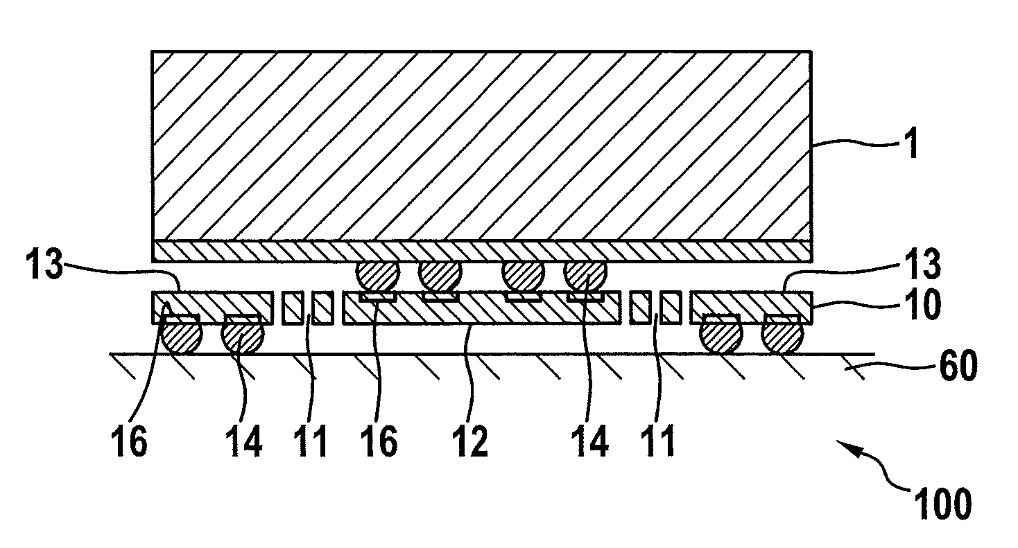
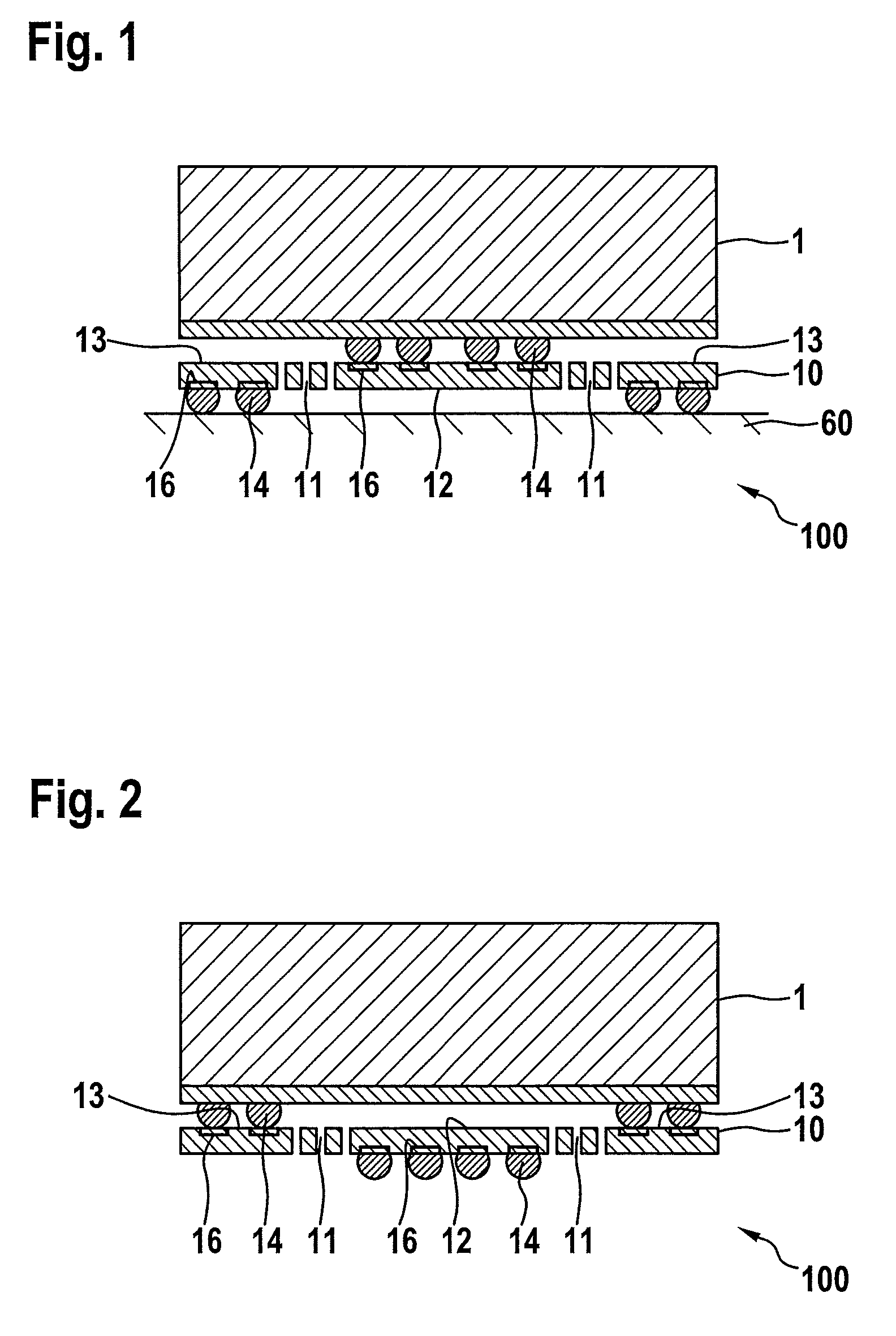
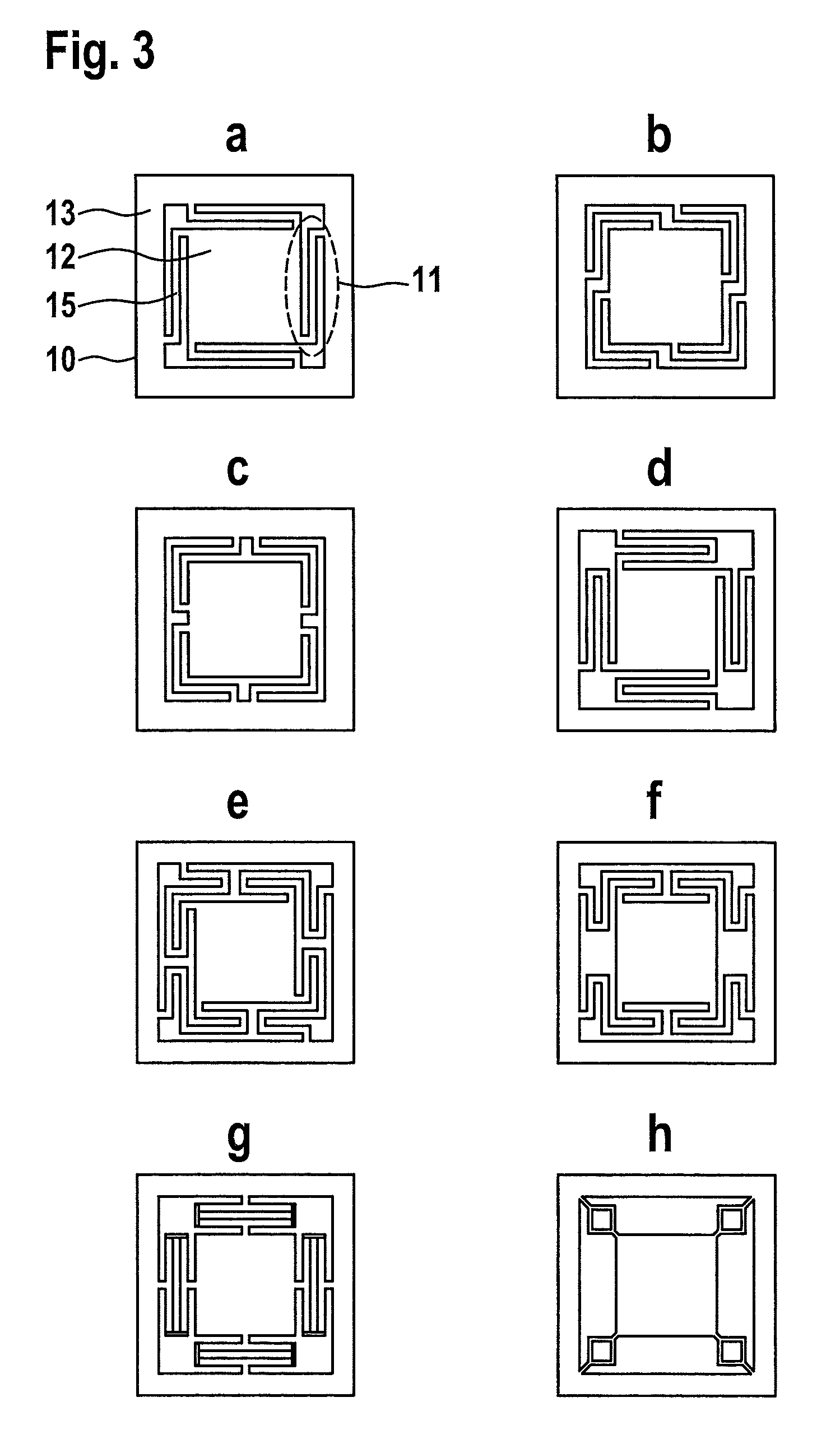
[0048]FIG. 1 shows a sectional view of one specific embodiment of damping device 100 according to the present invention. Damping device 100 has a first intermediate layer 10, having a printed circuit board material, which is subdivided by an elastic device 11 into a centrally situated first section 12 and a second section 13 which surrounds first section 12 in a ring-like manner. A lateral distance is thus formed between the two mentioned sections 12, 13, i.e., the two substrate parts.

[0049]Contacting elements 14 are situated on a bottom side of second section 13 of first intermediate layer 10. However, contacting elements 14 may also optionally be situated on a surface of a printed circuit board 60 on which the arrangement composed of sensor device 1 and damping device 100 is mounted. Contacting elements 14 are also situated on a printed circuit board substrate on which sensor device 1 is mounted, and therefore, also on a top side of first section 12 of first intermediate layer 10....


PUM

PropertyMeasurementUnit
frequencyaaaaaaaaaa
frequencyaaaaaaaaaa
diameteraaaaaaaaaa

Abstract

A damping device for a micromechanical sensor device, having at least one first intermediate layer having at least two sections, a second section being situated around a first section, a lateral distance being provided between the first and the second section, and an elastic device being provided between the first section and the second section as an integral part of the first intermediate layer.

Description

CROSS REFERENCE[0001]The present application claims the benefit under 35 U.S.C. §119 of German Patent Application No. DE 102012201486.1 filed on Feb. 2, 2012, which is expressly incorporated herein by reference in its entirety.FIELD[0002]The present invention relates to a damping device for a micromechanical sensor device.BACKGROUND INFORMATION[0003]In the packaging of micromechanical sensors, it is sometimes absolutely necessary to keep interfering vibrations away from the sensitive sensor element. The micromechanical sensors (for example, inertial sensors such as yaw rate sensors and acceleration sensors) are exposed to different stresses at an intended installation site in a motor vehicle as the result of various influences. One particular influence is vibration stress which occurs, among other elements, in high-resolution inertial sensors for ESP applications in a control unit. To protect or to decouple the sensors from these vibrations, specialized damping structures and materi...

Claims


Application Information

Patent Timeline
Patent Type & Authority Patents(United States)
IPC IPC(8): G01P1/00H05K3/00G01P15/08H05K1/14H05K1/02
CPCG01P1/003G01P15/0802H05K1/141H05K3/00Y10T29/4913H05K1/0271H05K2201/049H05K2201/10151G01P2015/0882H01L2224/16225H01L2924/15311
Inventor HOEFER, HOLGEREHRENPFORDT, RICARDOOFFTERDINGER, KLAUSSOLF, CHRISTIAN
Owner ROBERT BOSCH GMBH
Why Eureka
Try Eureka