Motor drive injection unit, die cast machine having the unit, and motor drive injection method

a technology of injection unit and injection piston, which is applied in the direction of casting apparatus, molten metal supply equipment, manufacturing tools, etc., can solve the problems of inability to accurately transmit the drive force, the injection piston is applied too much force, and the injection piston is not suitable for us

Inactive Publication Date: 2007-06-05
YKK CORP
View PDF4 Cites 3 Cited by
  • Summary
  • Abstract
  • Description
  • Claims
  • Application Information

AI Technical Summary

Benefits of technology

[0010]An object of the present invention, which was made to satisfy the above requirement, is to provide a motor drive injection unit and a motor drive injection method which can obtain an injection speed suitable for a molding material having a fast solidifying speed as in, for example, a die cast machine as well as can securely keep pressure for a predetermined period of time while making the position of an injection piston unmovable after injection and filling are completed.
[0014]Further, another part of the object can be effectively achieved by a joint interposed between the plunger and the injection piston and fixedly disposed to an end of the plunger as well as holding the base end portion of the injection piston in a hollow portion in which the base end portion can relatively reciprocate within a necessary distance. These motor drive injection units are preferably applied to a die cast machine.
[0015]In contrast, the above object can be achieved by the basic configuration of a motor drive injection method of the present invention which injects a molding material in a cylinder into a metal mold by converting the rotational motion of an electric servo motor into the reciprocating motion of an injection piston coupled with a plunger to which a ball screw threaded into a ball nut portion is formed, the method including the steps of increasing the rotation speed of the electric servo motor to an injection speed of the injection piston, and injecting a molding material in a cylinder in a short time by increasing the initial speed of the injection piston by providing a predetermined time difference between the motion of the plunger in an injecting direction and the injecting motion of the injection piston.

Problems solved by technology

However, the hydraulic cylinder is used in the die cast machine in order to prevent a situation that an apparatus is deformed or damaged since when a heating by a heater is stopped upon molding a molding material (molten material), which is expanded by cooling, the molten material in a holding furnace is solidified as well as the molten material in an injection cylinder is also solidified and expanded and an excessive force is applied to an injection piston in the injection cylinder.
This is because since rotation acceleration is constant when the injection piston is driven by the electric motor different from the hydraulic drive, a considerable time is required until a desired injection speed is obtained after the electric servo motor starts rotation.
In contrast, in the hydraulic drive system, although a required injection speed can be obtained promptly as described above, drive force cannot be accurately transmitted in many cases due to a change of viscosity of oil caused by a change of temperature thereof when, for example, an injection piston is driven, and further a working environment may be deteriorated by the oil.

Method used


Image

  • Motor drive injection unit, die cast machine having the unit, and motor drive injection method
  • Motor drive injection unit, die cast machine having the unit, and motor drive injection method
  • Motor drive injection unit, die cast machine having the unit, and motor drive injection method

Examples


Embodiment Construction

[0027]A typical embodiment of the present invention will be specifically explained below with reference to the drawings.

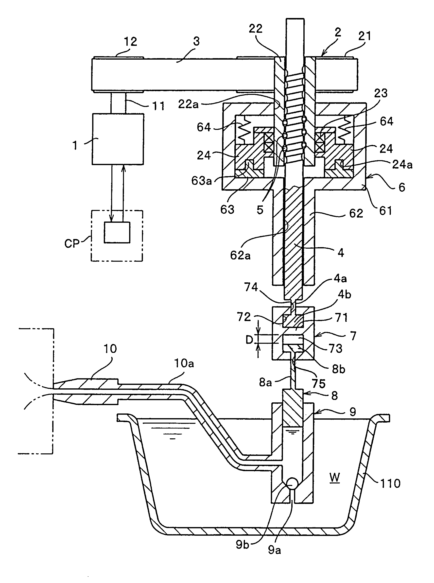
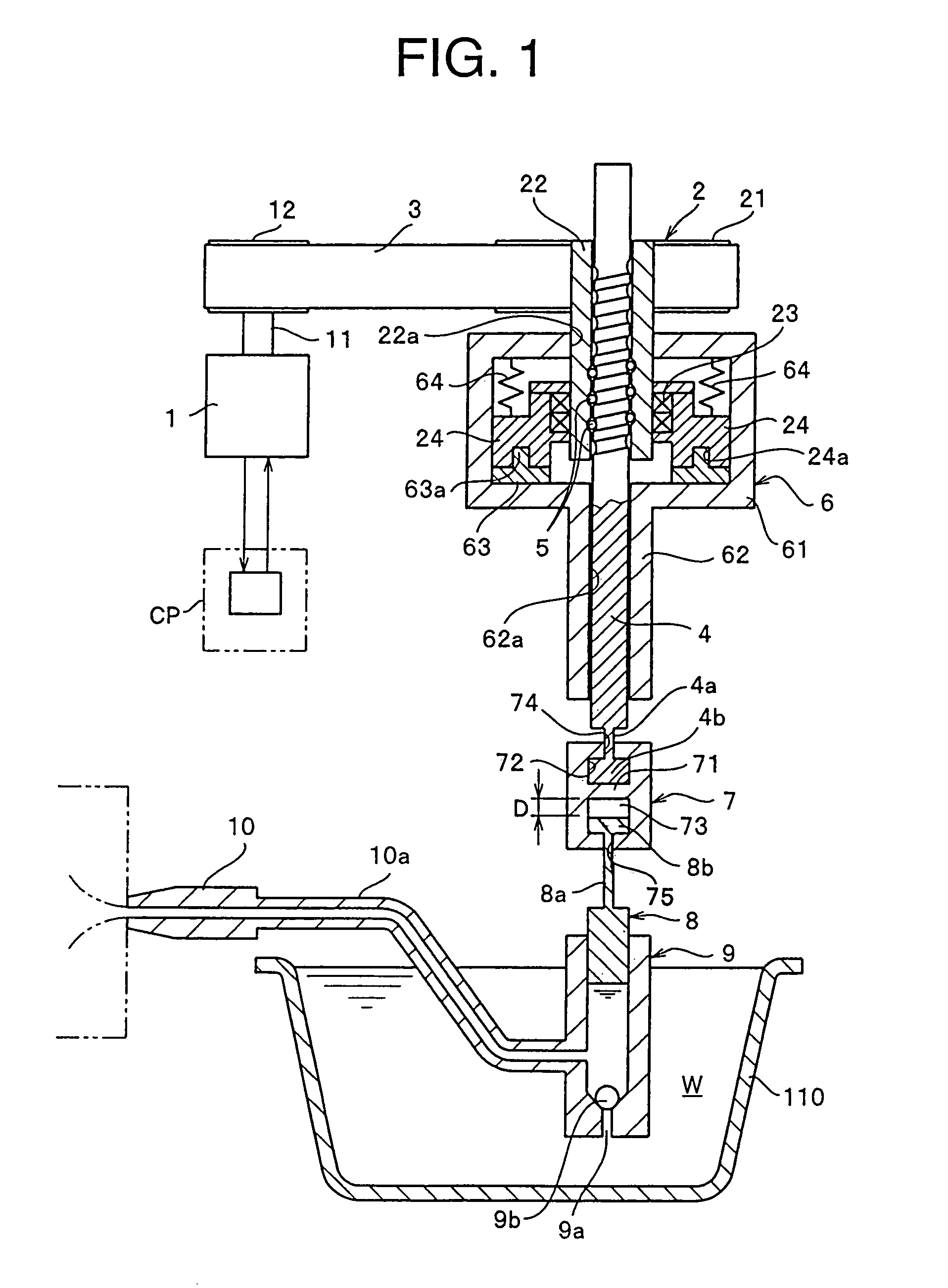
[0028]FIG. 1 schematically shows an overall configuration of a die cast machine having a motor drive injection unit of the invention. Note that the motor drive injection unit of the invention can be also applied to a transfer molding machine disclosed in, for example, the patent document 2 and further can be also applied to an ordinary vertical injection molding machine depending on a type of a molding material.

[0029]In FIG. 1, reference numeral 1 denotes an electric servo motor, and a first belt pulley 12 fixedly disposed to an output shaft 11 of the electric servo motor 1 is coupled with a ball nut member 2 through a belt 3. The ball nut member 2 includes a second belt pulley 21, a ball nut portion 22 whose upper end is fixedly disposed to the center of rotation of the second belt pulley 21, and a ball nut support portion 24 relatively rotatably coupled with the ...


PUM

PropertyMeasurementUnit
timeaaaaaaaaaa
timeaaaaaaaaaa
distanceaaaaaaaaaa

Abstract

In a motor drive injection unit and a motor drive injection method, which can obtain an injection speed suitable for a molding material having fast solidifying speed as well as can securely carry out pressure keeping for a predetermined period of time while making a position of an injection piston unmovable after injection and filling are completed, a molding material in a cylinder is injected into a metal mold by converting a rotational motion of an electric servo motor into a reciprocating motion of an injection piston in the cylinder through a plunger with a ball screw, a surge pressure control means is provided for placing the injection piston in the cylinder in an unmovable state when at least a predetermined amount of a load is applied to the injection piston by the molding material in the cylinder, the surge pressure control means includes a combination of rotation control means of the electric servo motor and an upward movement suppression mechanism of the injection piston, and further, an injection speed of the injection piston is increased by providing a time difference between initial motions of the plunger and the injection piston.

Description

BACKGROUND OF THE INVENTION[0001]1. Field of the Invention[0002]The present invention relates to an injection unit for making it possible to execute a high speed injection using an electric motor as well as to securely keep pressure after a metal mold is filled with a molding material, a die cast machine provided with the unit, and a motor drive injection method.[0003]2. Description of the Related Art[0004]Conventionally, in a die cast machine for injecting a molten metal material such as aluminum and zinc into a metal mold and molding it, an injection piston is ordinarily driven by hydraulic pressure because of a reason that the injection piston can be actuated at high speed and a structure is simple, and the like. For example, in a die cast machine disclosed in Japanese Utility Model Application Laid-Open (JP-U) No. 3-4349 (patent document 1), an injection piston is also driven using a hydraulic cylinder. However, the hydraulic cylinder is used in the die cast machine in order to ...

Claims


Application Information

Patent Timeline
Patent Type & Authority Patents(United States)
IPC IPC(8): B22D17/08B22D17/12
CPCB22D17/04B22D17/203B22D39/02
Inventor MIYAZAKI, TATSUYOSHIISHIKAWA, TAKESHI
Owner YKK CORP
Why Eureka
Try Eureka