

Magnetic read/write apparatus having a write inhibit slice setting circuit
a technology of write inhibiting and read/write apparatus, which is applied in the direction of maintaining head carrier alignment, digital recording, instruments, etc., can solve the problems of gradually erasing the data in the neighboring sector (tracks), and achieve the effect of preventing the erasure of written data, reducing the decrease in the data transfer rate, and high track density
- Summary
- Abstract
- Description
- Claims
- Application Information
AI Technical Summary
Benefits of technology
Problems solved by technology
Method used
Image

Examples
first embodiment
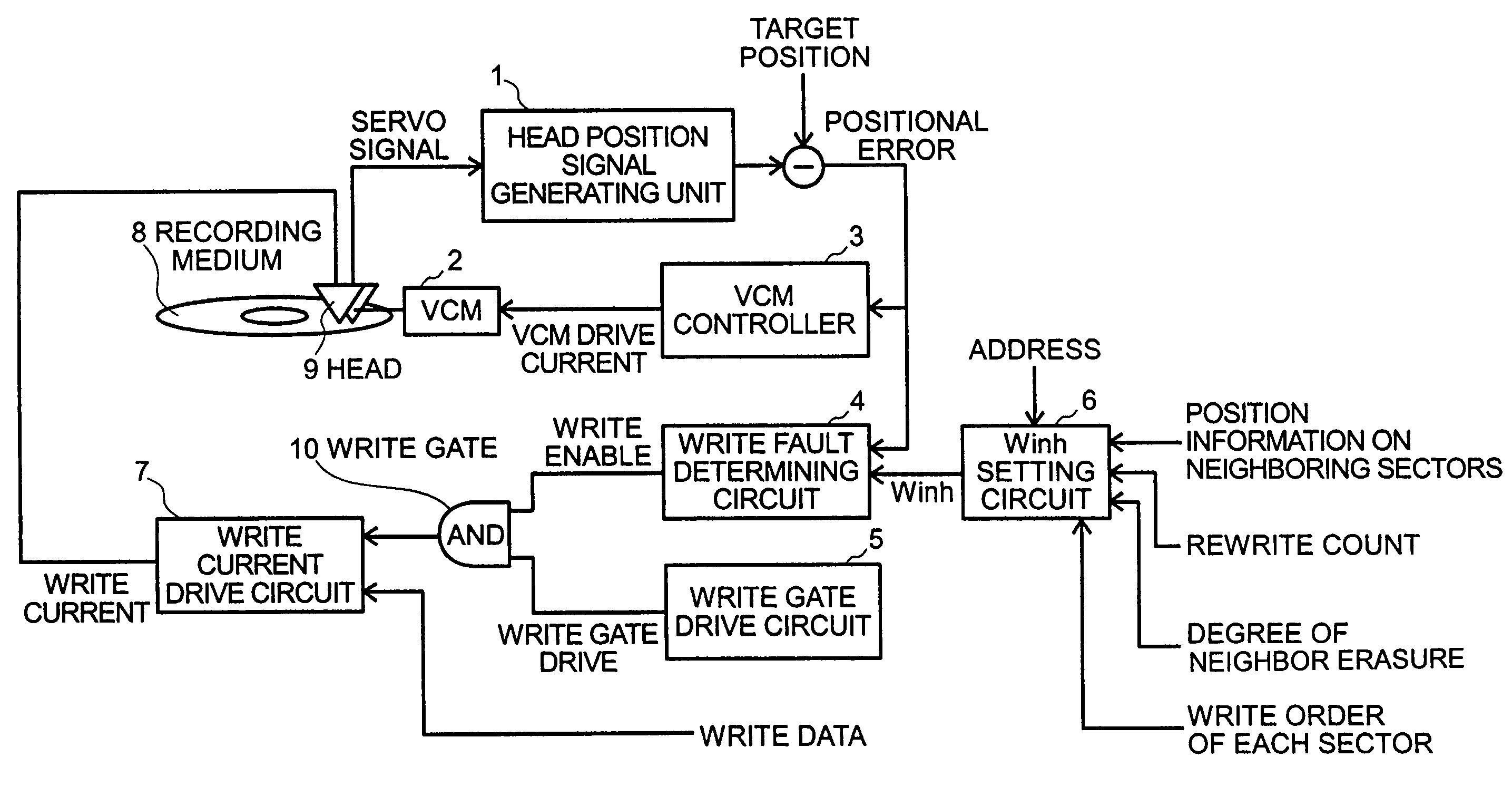
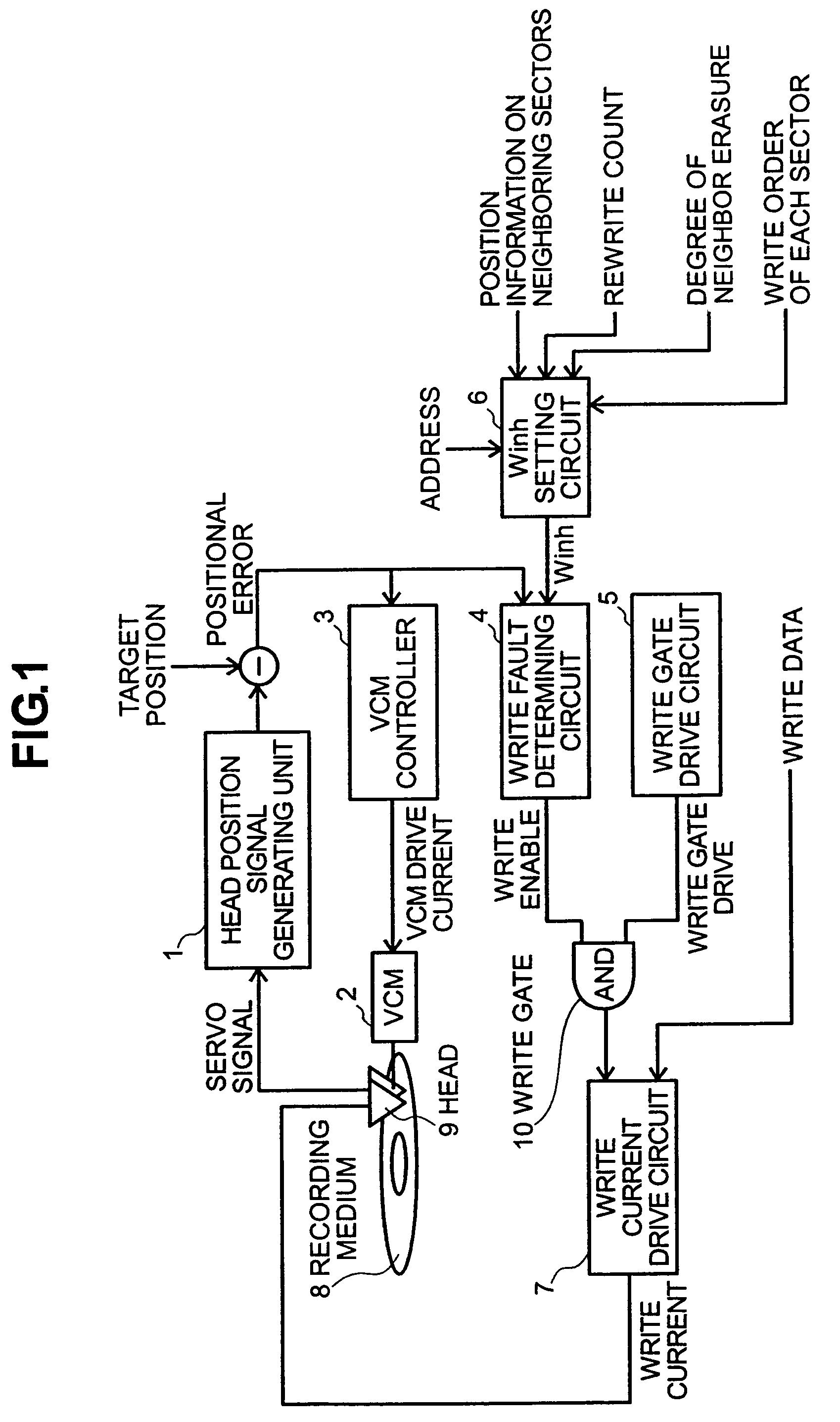
[0041]FIG. 1 is a diagram showing the configuration of a magnetic read / write apparatus according to a first embodiment of the present invention.
[0042]Referring to the figure, the magnetic read / write apparatus comprises a head position signal generating unit 1, a VCM (voice coil motor) 2, a VCM controller 3, a write fault determining circuit 4, a write gate drive circuit 5, a Winh (write inhibit slice) setting circuit 6 (write inhibit slice setting means), a write current drive circuit 7, a recording medium 8, a head 9, and a write gate 10. The Winh setting circuit 6 receives: an address; the write order of each sector (information on the write order is written on a sector basis); position information on neighboring sectors such as the amount of displacement of the write position of each neighboring sector from the center of its track; information on the degree of “proximity erasure” (erasure of neighboring tracks) by each head 9; and information on the rewrite counts of neighboring ...
second embodiment
[0078]According to the first embodiment, the Winh setting circuit 6 receives: an address; the write order of each sector (information on the write order is written on a sector basis); position information on neighboring sectors such as the amount of displacement of the write position of each neighboring sector from the center of its track; information on the degree of proximity erasure by each head 9; and information on the rewrite counts of neighboring sectors. The Winh setting circuit 6 then sets a write inhibit slice for each sector based on these pieces of information. The second embodiment, on the other hand, uses a write inhibit slice setting table to set a write inhibit slice (Winh).
[0079]FIGS. 11 and 12 are diagrams showing an example of how to set write inhibit slices according to the second embodiment.
[0080]Specifically, in the example shown FIGS. 11 and 12, write inhibit slices are set when sectors are written on a track A. FIG. 11 only shows sectors on the left side of a...
third embodiment
[0093]According to a third embodiment of the present invention, information on the write order and write position of each sector is stored in a RAM (memory means) in the magnetic read / write apparatus, and a write inhibit slice (Winh) is set based on this information.
[0094]FIG. 13 is a diagram showing the configuration of a magnetic read / write apparatus according to the third embodiment of the present invention.
[0095]Referring to the figure, the magnetic read / write apparatus comprises: a RAM 20 for storing information on the write order and the write position of each sector; and a target position specifying unit 21 for specifying a target position based on an address. The rest of the configuration is the same as that of the first embodiment.
[0096]Description will be made below of the operation of the present embodiment.
[0097]FIG. 14 is a flowchart showing the operation performed when data is written according to the third embodiment.
[0098]When a data write instruction has been issued...
PUM
| Property | Measurement | Unit |
|---|---|---|
| area | aaaaa | aaaaa |
| track density | aaaaa | aaaaa |
| displacement | aaaaa | aaaaa |
Abstract
Description
Claims
Application Information