Magnetic disc apparatus and magnetic head in which a recording/reproduction element is mounted on a slider via a piezoelectric element

a piezoelectric element and magnetic disc technology, applied in the direction of manufacturing head surfaces, recording information storage, and maintaining head carrier alignment, can solve the problems of increasing the difficulty of performing track positioning with a high speed and a high accuracy, and the difficulty of simultaneously improving linear recording density and track density, and achieve high mechanical reliability. , the effect of high recording density

Inactive Publication Date: 2005-08-16
TDK CORPARATION
View PDF18 Cites 18 Cited by
  • Summary
  • Abstract
  • Description
  • Claims
  • Application Information

AI Technical Summary

Benefits of technology

[0033]It is therefore an object of the present invention to provide a magnetic head capable of following a swell of the roughness of a magnetic disc with a small spacing so as to increase linear recording density and. Another object of the present invention is to provide a magnetic head capable of positioning with a high accuracy in the magnetic disc radial direction, thereby increasing track density. Furthermore, it is an object of the present invention to provide a magnetic head having small spacing and capable of positioning with a high accuracy in the magnetic disc radial direction, thereby simultaneously increasing the linear recording density and the track density. Moreover, the present invention provides a magnetic head production method appropriate for mass production of magnetic heads and provides a magnetic disc apparatus using magnetic heads.

Problems solved by technology

However, when the floating power is weakened, the spacing cannot follow a surface configuration (wavelength from micrometers to millimeters, frequency from several tens of kHz to several hundreds of kHz) of a dimension similar to that of the magnetic head slider.
Moreover, the magnetic head may be brought into contact with the magnetic disc, causing friction.
Accordingly, it is difficult to perform track positioning with a high speed and a high accuracy.
Accordingly, it becomes more difficult to perform a track positioning with a high accuracy.
Thus, in the conventional magnetic disc apparatus, it has been difficult to simultaneously improve the linear recording density and the track density.
The technique described in Document [2], i.e., the technique to drive a magnetic head into the spacing direction by the piezoelectric actuator has a problem that it is difficult to follow the magnetic disc swell (amplitude of 1 to 10 micrometers, wavelength of several tens to hundreds of mm, and frequency of several tens to hundreds of Hz) only by the piezoelectric actuator.
Accordingly, a piezoelectric element and a recording / reproduction element are mounted on each magnetic head slider, which is not appropriate for a mass production of magnetic heads.
The technique to drive the support spring supporting a magnetic head slider, by an electromagnetic actuator, and the technique to drive the entire magnetic head slider by a piezoelectric element beam have a problem that a resonance frequency is too low.
Moreover, since the drive source is apart from the recording / reproduction element, there is a problem that there arises a delay of a reproduction signal used for a position detection information.
The technique to drive a recording / reproduction element by an electrostatic actuator provided at the rear end of the slider has a problem that a flexible spring structure is used and resonance frequency is too low, and because the drive force is small, it is difficult to drive the recording / reproduction element at a high speed.
The head slider described in Document [7] can perform positioning in the track direction but cannot control the spacing direction.
The magnetic recording / reproduction apparatus described in Document [8] can perform a multi-element simultaneous tracking but cannot perform control in the spacing direction.
Accordingly, it is necessary to mount a piezoelectric element and a recording / reproduction element for each slider, which is not appropriate for mass production of the magnetic head.
However, with the conventional techniques, it is difficult to increase the track positioning accuracy in such a minimum spacing state.

Method used


Image

  • Magnetic disc apparatus and magnetic head in which a recording/reproduction element is mounted on a slider via a piezoelectric element
  • Magnetic disc apparatus and magnetic head in which a recording/reproduction element is mounted on a slider via a piezoelectric element
  • Magnetic disc apparatus and magnetic head in which a recording/reproduction element is mounted on a slider via a piezoelectric element

Examples


first embodiment

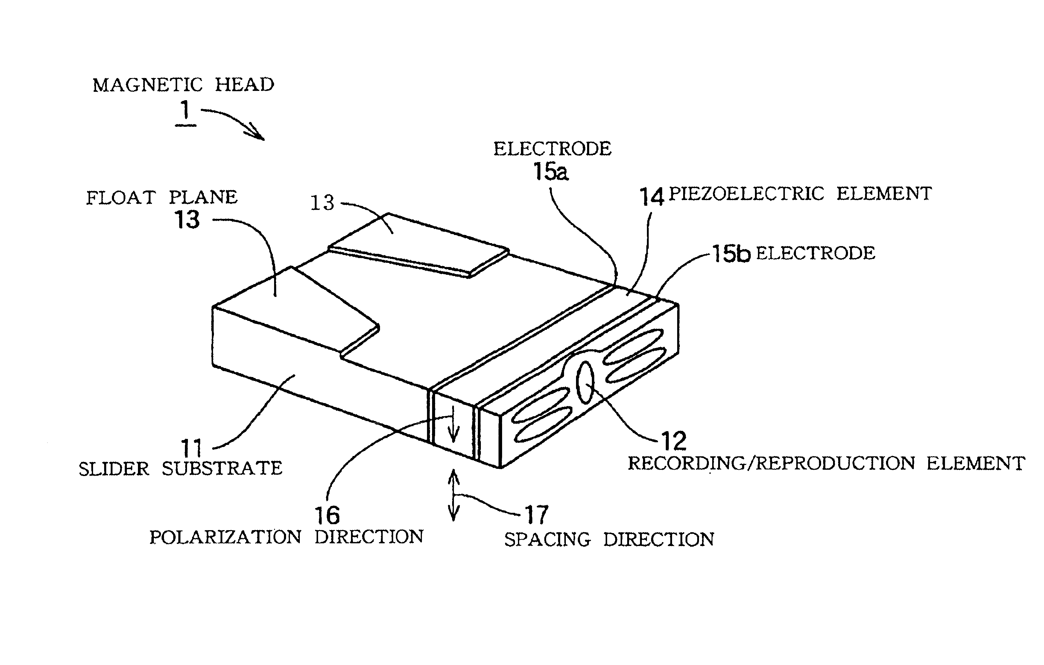
[0070]FIG. 1 is a perspective view of a magnetic head (magnetic head slider) according to the present invention. FIG. 1 shows a magnetic head floating plane (facing a magnetic disc) upward. The magnetic head (magnetic head slider) shown in FIG. 1 includes a slider substrate 11, a piezoelectric element 14 sandwiched by electrodes 15a and 15b, and a recording / reproduction element 12. A floating plane 13 is formed on the surface of the slider substrate 11.

[0071]The piezoelectric element 14 is attached to the rear end surface (air flow out side) of the slider substrate 11 via one of the electrodes 15a. On the side of the other electrode 15b of the piezoelectric element 14, the recording / reproduction element 12 is arranged.

[0072]The piezoelectric element 14 is displaced when an electric field is applied between the electrodes 15a and 15b. In the case when the polarization direction 16 of the piezoelectric element 14 is vertical to the electric field, the piezoelectric element 14 is displ...

second embodiment

[0082]FIG. 3 is a perspective view of a magnetic head (magnetic head slider) according to the present invention. In the magnetic head (magnetic head slider) 2 shown in FIG. 3, a floating plane 13 is formed on the surface of the slider substrate 11. Moreover, in this magnetic head (magnetic head slider) 2, a piezoelectric element 141 sandwiched by electrodes 15a and 15b is attached to the rear surface of the slider substrate 11 and a recording / reproduction element 12 is arranged via the piezoelectric element 141. The piezoelectric element 141 has a polarization direction 161 vertical to the direction of the electric field.

[0083]In the magnetic head (magnetic head slider) 2 shown in FIG. 3, the polarization direction 161 of the piezoelectric element 141 is the radial direction (track direction) of a magnetic disc. Accordingly, by applying an electric field between the electrodes 15a and 15b, it is possible to displace the recording / reproduction element 12 in the track direction. The e...

third embodiment

[0089]FIG. 4 is a perspective view of a magnetic head (magnetic head slider) according to the present invention. In the magnetic head (magnetic head slider) 3 shown in FIG. 4, a floating plane 13 is formed on the surface of the slider substrate 11. Moreover, in this magnetic head (magnetic head slider) 3, on the rear surface of the slider substrate 11, a piezoelectric element 14 sandwiched between an electrode 15a and a common electrode 15b and a piezoelectric element 141 sandwiched by the common electrode 15b and an electrode 15c are layered, and a recording / reproduction element 12 is arranged on the electrode 15c.

[0090]The piezoelectric element 14 has the polarization direction 16 in the spacing direction 17, and the piezoelectric element 141 has the polarization direction 161 in the track direction 18. Thus, the polarization directions 16 and 161 of the two piezoelectric elements 14 and 141 are in the spacing direction 17 and the track direction 18 which are perpendicular to eac...


PUM

PropertyMeasurementUnit
wavelengthaaaaaaaaaa
resonance frequencyaaaaaaaaaa

Abstract

A recording / reproduction element is mounted on a magnetic head slider via a piezoelectric element so that a displacement of the piezoelectric element performs fine control of the position of the recording / reproduction, thus enabling fine spacing and high track positioning accuracy. This improves linear recording density and track density. A pair of electrodes are formed on both sides of a piezoelectric element to constitute a piezoelectric actuator. One electrode is arranged opposite the rear surface (air flow out end) of a magnetic head slider 11. A recording / reproduction element is arranged on and electrically insulated from the other electrode. The piezoelectric element includes a piezoelectric element displaced in a spacing direction, enabling fine spacing control, a piezoelectric element displaced in the track direction, enabling a fine track position control, and a piezoelectric element displaced in a magnetic disc rotation direction, enabling reduction of jitter of a reproduction signal.

Description

[0001]The present Application is a divisional Application of prior U.S. application Ser. No. 09 / 587,132 filed Jun. 2, 2000 now U.S. Pat. No. 6,487,045.BACKGROUND OF THE INVENTION[0002]1. Field of the Invention[0003]The present invention relates to a magnetic disc apparatus, a magnetic head, and an each production method thereof and in particular, to a magnetic head in which a recording / reproduction element is mounted on a magnetic head slider via a piezoelectric element so that the position of the recording / reproduction element can be adjusted in job mode by displacement of the piezoelectric element, and its production method, a magnetic disc apparatus using the magnetic head, and its production method.[0004]2. Description of the Related Art[0005]In a magnetic disc apparatus, recording density can be increased by increasing the recording density (linear recording density) of the magnetic disc rotation direction and the recording density (track density) of the magnetic disc radial di...

Claims


Application Information

Patent Timeline
Patent Type & Authority Patents(United States)
IPC IPC(8): G11B5/55G11B5/60G11B21/10G11B21/21
CPCG11B5/5552G11B5/6005Y10T29/49025Y10T29/49041Y10T29/42Y10T29/49032Y10T29/49046Y10T29/49048Y10T29/49052Y10T29/49043Y10T29/49798
Inventor YANAGISAWA, MASAHIRO
Owner TDK CORPARATION
Why Eureka
Try Eureka