Magnetic head for perpendicular recording including a main pole having a pole tip with three tapered sides

Inactive Publication Date: 2006-05-02
HITACHI LTD
View PDF18 Cites 17 Cited by
  • Summary
  • Abstract
  • Description
  • Claims
  • Application Information

AI Technical Summary

Benefits of technology

[0012]In the magnetic head for perpendicular recording according to the invention, at least one or more sides of the main pole except for the trailing side are tapered with an appropriate angle against the tip surface, and the yoke of which widest principal plane is in parallel to the tip surface is provided on the bottom of the main pole. Concretely, the perpendicular recording head includes the main pole, and the yoke (first yoke) provided on the opposite side to the tip surface of the main pole that faces the perpendicular recording medium. In this construction, the principal plane having the widest area in the yoke is in parallel to the tip surface. And, at least more than one of the sides of the main pole except

Problems solved by technology

However, the surface recording method in the current state has a problem that, when the recorded bit length decreases, it becomes extremely difficult to increase the surface recording density due to the thermal fluctuation of magnetization of a medium.
However, to decrease the area of the tip surface of the single pole magnetic head will reduce the possibly generated magnetic field strength substantially in inverse proportion to the area thereof, which will hinder a sufficient recording.
The first method of solving this problem is to increase the saturation magnetic flux density Bs of a magnetic material making up the single pole magnetic head; however, the theoretical limit of the saturation magnetic flux density Bs of a magnetic material is 3.0 tesla, which is only 1.5 times the magnetic flux density of the currently used material, and it is impossible to meet a demand for future high density.
However, these conventional proposals involve the following problems.
The method of providing a thin film to the tip surface area of the main pole of a perpendicular magnetic head, further providing a mi

Method used


Image

  • Magnetic head for perpendicular recording including a main pole having a pole tip with three tapered sides
  • Magnetic head for perpendicular recording including a main pole having a pole tip with three tapered sides
  • Magnetic head for perpendicular recording including a main pole having a pole tip with three tapered sides

Examples


first embodiment

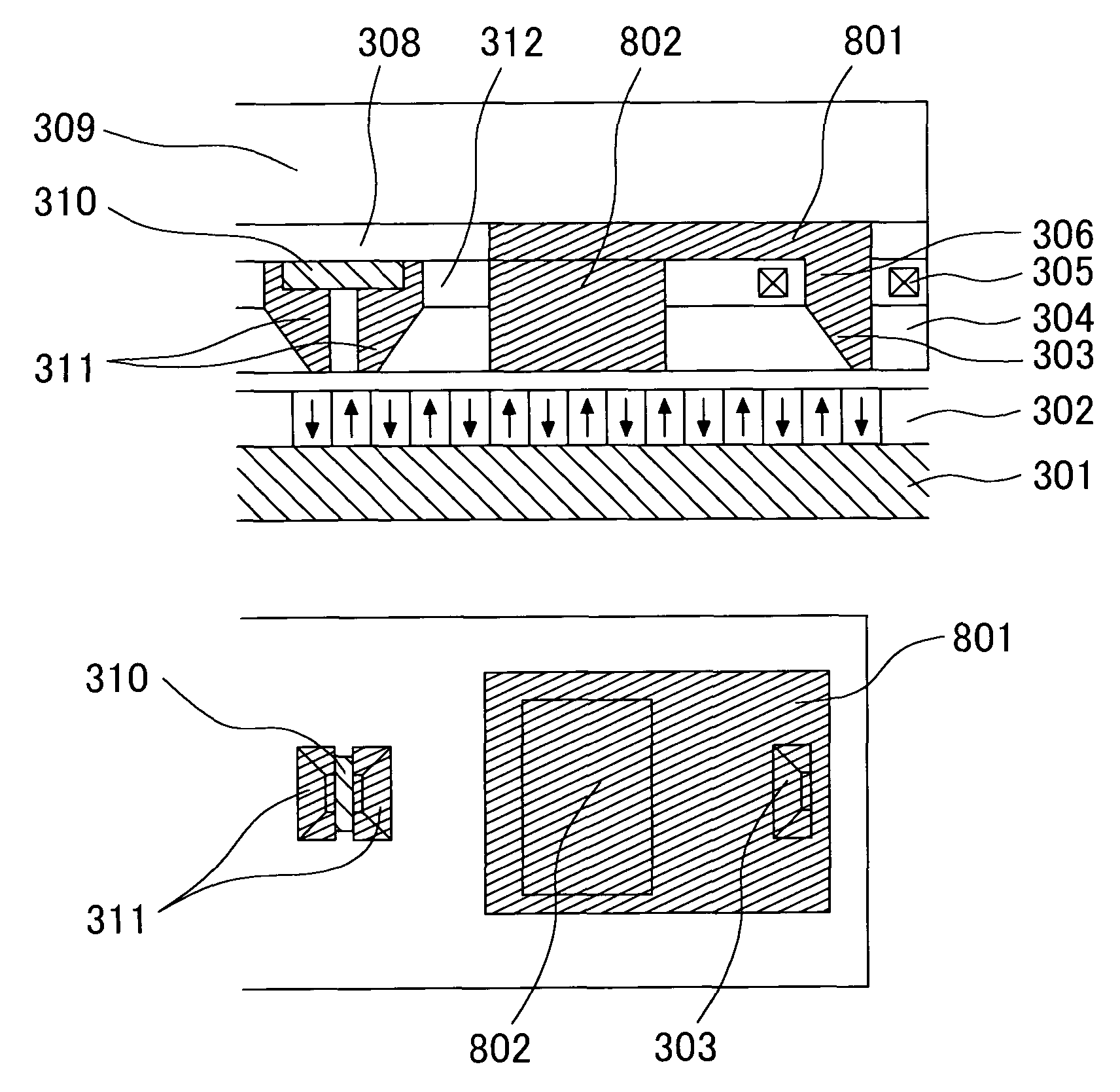
[0041]FIGS. 3A and 3B schematically illustrate the magnetic head for perpendicular recording according to the invention. FIG. 3A is a sectional view, and FIG. 3B is a plan view (here, the magnification is not uniform in these drawings). In FIGS. 3A and 3B, the numeric symbol 301 denotes a soft magnetic backing layer, 302 a perpendicular recording medium, 303 a main-pole taper part of the magnetic head for perpendicular recording, 304 an inorganic insulating layer, 305 a coil for exciting magnetic fluxes in the main pole, and 306 a main pole body. In this embodiment, the coil is wound by one turn virtually around the main pole body, in parallel to the tip surface of the magnetic head for perpendicular recording; however the number of turns of the coil may be two or more.

[0042]The numeric symbol 307 denotes a first yoke disposed substantially in parallel to the surface of the recording medium, 308 an inorganic insulating layer for embedding the yoke, formed on a substrate 309, 310 a r...

third embodiment

[0055]The numeric symbol 307 denotes the yoke disposed substantially in parallel to the surface of the recording medium, 308 the inorganic insulating layer for embedding the yoke, formed on the substrate 309, 310 the reproduction head using the magnetoresistance effect such as the AMR, GMR, TMR, or the like, 312 the inorganic insulating layer for embedding the coil, and 901 a yoke (second yoke) for introducing the magnetic fluxes from the magnetic recording medium into the reproduction head. Thus, the third embodiment is characterized in that the second yoke 901 is made up with one piece of magnetic substance having substantially the same structure as the taper part of the main pole.

[0056]FIGS. 10A and 10B illustrate schematic drawings of a magnetic head for perpendicular recording of the fourth embodiment (here, the magnification of the drawing is not uniform). FIG. 10A is a sectional view, and FIG. 10B is a plan view. In FIGS. 10A and 10B, the numeric symbol 301 denotes the soft m...


PUM

PropertyMeasurementUnit
Angleaaaaaaaaaa
Angleaaaaaaaaaa
Angleaaaaaaaaaa

Abstract

The invention provides a magnetic head for perpendicular recording capable of recording with high linear recording density and high track density, and a magnetic disk drive incorporating the same. In order to achieve this, one or more sides of the main pole of the magnetic head for perpendicular recording except for the trailing side are formed in a taper with an appropriate angle against the tip surface of the main pole, and the yoke whose widest principal plane is in parallel to the tip surface is provided on the bottom of the main pole.
Thereby, the invention achieves the magnetic head for perpendicular recording that generates a sufficiently high magnetic field, and assumes a sharp gradient of magnetic field on the trailing side. By incorporating this magnetic head, a magnetic disk drive capable of handling high linear recording density can be produced.

Description

BACKGROUND OF THE INVENTION[0001]1. Field of the Invention[0002]The present invention relates to a magnetic head for perpendicular recording, a method of manufacturing the same, and a magnetic disk drive incorporating the same.[0003]2. Description of the Related Art[0004]The surface recording density of a magnetic disk drive has been increasing steadily, and it is estimated to reach 100 gigabits per square inch in 2003. However, the surface recording method in the current state has a problem that, when the recorded bit length decreases, it becomes extremely difficult to increase the surface recording density due to the thermal fluctuation of magnetization of a medium. In order to solve this problem, the perpendicular recording method that records magnetization signals in the direction perpendicular to the medium has been drawing wide attentions. Especially, the perpendicular recording method that uses a perpendicular recording medium having a soft magnetic backing layer as the magne...

Claims


Application Information

Patent Timeline
IPC IPC(8): G11B5/187G11B5/39G11B5/00G11B5/31G11B5/012G11B5/127G11B5/48
CPCG11B5/012G11B5/1278Y10T29/49052G11B5/4886G11B2005/0029G11B5/1871
Inventor ITO, KENCHIKAWATO, YOSHIAKIMOCHIZUKI, MASAFUMI
Owner HITACHI LTD
Why Eureka
Try Eureka