Electromagnetic heads, flexures, gimbals and actuators formed on and from a wafer substrate

a technology of gimbals and actuators, which is applied in the field of gimbals and flexures, can solve the problems of reducing the accuracy of gimbals, reducing the mass and moment arms of gimbals, and destroying sensors, etc., so as to increase the accuracy, and reduce the mass and moment arms

Inactive Publication Date: 2007-07-24
LAUER MARK A
View PDF46 Cites 18 Cited by
  • Summary
  • Abstract
  • Description
  • Claims
  • Application Information

AI Technical Summary

Benefits of technology

[0010]In accordance with the present invention integrated head, flexure, gimbal and / or actuator devices formed on and from a wafer substrate are disclosed. Conventional problems of connecting the head to the flexure and / or gimbal are reduced or eliminated, as all of these elements may be made on and from the same wafer on which the transducer is formed. The transducer layers may be oriented generally perpendicular to the media surface, affording employment of the most proven high-resolution transducer designs. Electrical leads may also be formed on the integrated flexure and / or gimbal in contact with leads of the head. Additionally, a microactuator may be formed on an end of the structure furthest from the transducer layers, providing a relatively simple mechanism for greatly increasing the accuracy with which the transducer is positioned adjacent media tracks and increasing track density.
[0011]Heads formed in accordance with the present invention can be made thinner and do not need a large area on the trailing surface for bonding pads, reducing their mass and moment arms. The gimbals and flexures can be more closely aligned with forces arising from interaction of the head with the disk surface and from seeking various tracks, reducing torque and dynamic instabilities. Alignment of a plane of the flexures between the actuator and the head greatly reduces low frequency vibrations due to actuation, as motion induced by the actuator is confined to a stiff in-plane direction as opposed to a flexible out-of-plane direction of the flexures. Spacing between disks can be reduced due to the thinner heads and lower profile gimbals and flexures. The heads may be operated in continuous or intermittent operational contact with the media, or may be designed to avoid such contact during operation. This brief summary merely lists a few possible features of the invention, which is described in more detail below.

Problems solved by technology

Care is usually taken to avoid sensor contact with a rapidly spinning rigid disk, as such contact may destroy the sensor or create false signal readings.
As heads become smaller, connection of even modern wireless suspensions becomes difficult and may add undesirable mechanical complexities to the gimbal area.
Moreover, MR sensors can be delicate and require at least two extra leads that must be connected to the drive electronics, adding to connection difficulties.
Additionally, as heads are required to fly closer to the media and provide quicker access time to various tracks on the disk, mechanical challenges increase.
Some of these proposed microactuators, however, interfere with flexure and gimbal mechanics, such as devices that rotate a head relative to an attached flexure.

Method used


Image

  • Electromagnetic heads, flexures, gimbals and actuators formed on and from a wafer substrate
  • Electromagnetic heads, flexures, gimbals and actuators formed on and from a wafer substrate
  • Electromagnetic heads, flexures, gimbals and actuators formed on and from a wafer substrate

Examples


Embodiment Construction

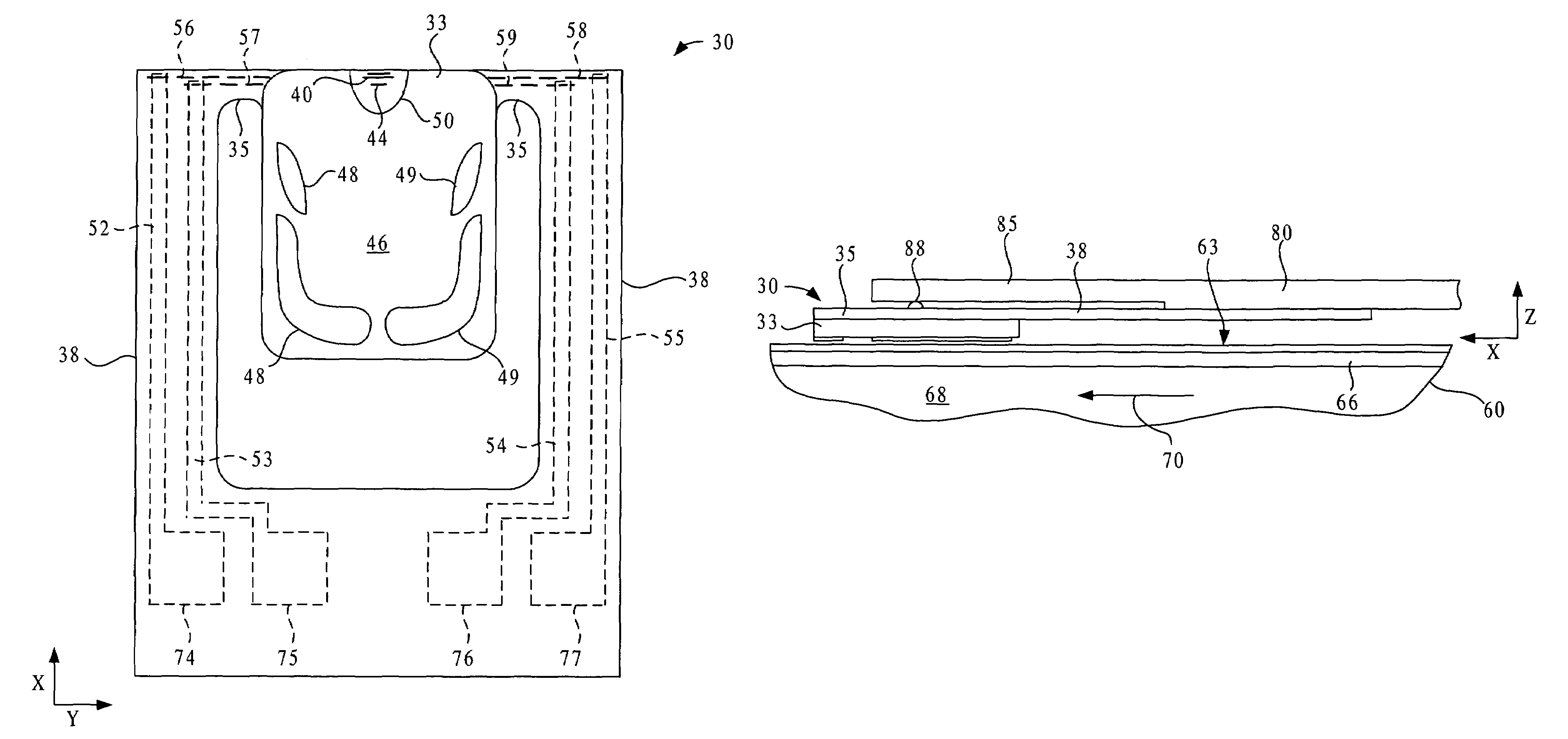
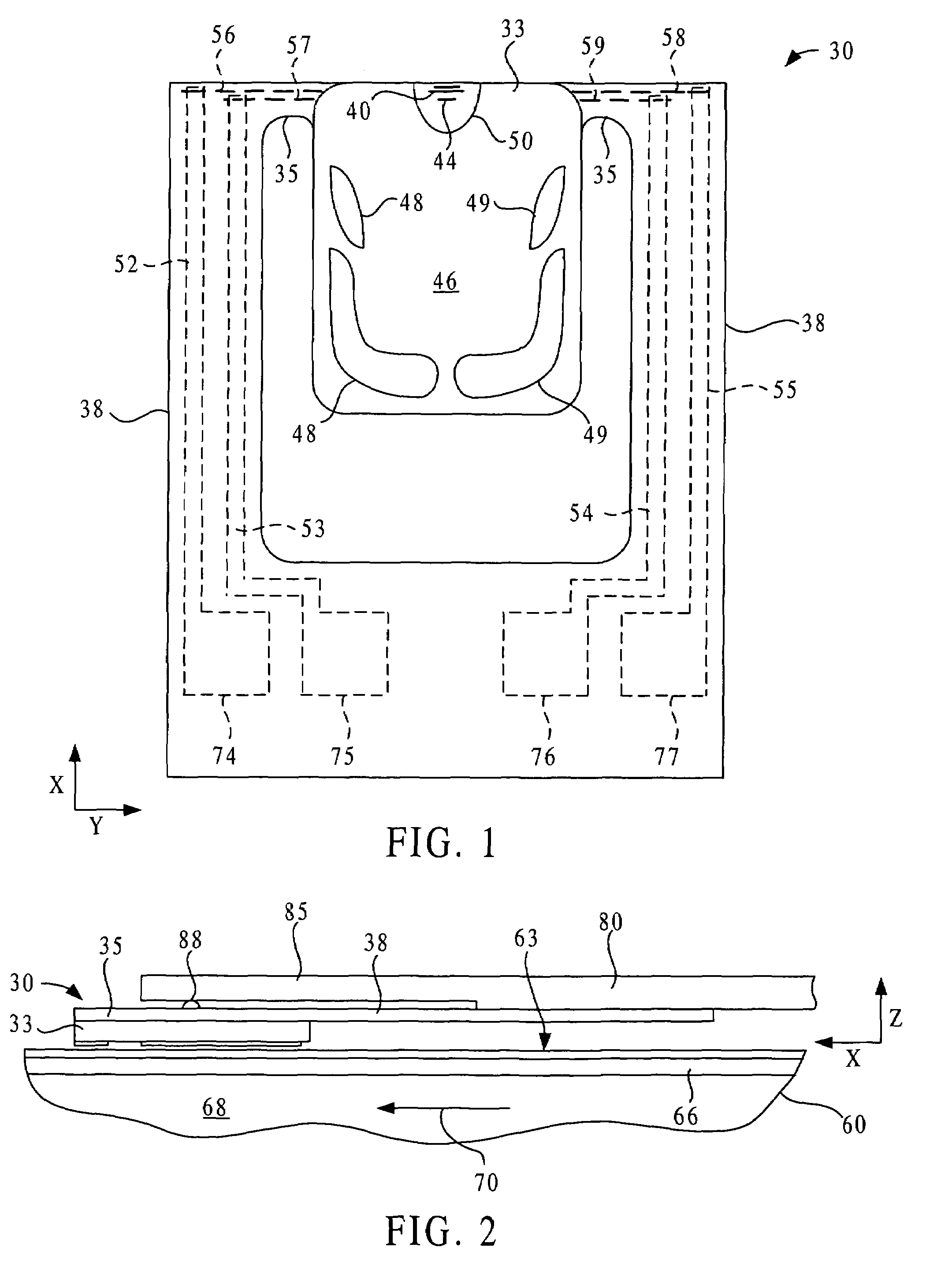
[0040]FIG. 1 shows a media-facing side of a device 30 of the present invention including an integrated head 33, gimbal 35 and flexure 38. The head 33 includes an inductive transducer 40 and a magnetoresistive (MR) transducer 44, although other types of transducers may alternatively be employed. As will be explained in greater detail below, the transducers 40 and 44 are formed along with many other similar transducers on a wafer substrate, after which the wafer is cut into rows each containing a number the transducers, and the rows are then processed from another direction to form the integrated head 33, gimbal 35 and flexure 38.

[0041]A media-facing surface 46 of the head 33 includes rails 48 and 49 and a transducer-containing pad 50 that are designed to be closer than the remainder of the media-facing surface to the media during operation. The rails 48 and 49 and pad 50 may project about a micron or less from the remainder of the bearing surface 46. The gimbal 35 and flexure 38 are ...


PUM

PropertyMeasurementUnit
thicknessaaaaaaaaaa
heightaaaaaaaaaa
temperaturesaaaaaaaaaa

Abstract

Devices for reading or writing electromagnetic information include a wafer substrate piece disposed between an electromagnetic transducer and an electrostrictive or piezoelectric actuator. The substrate piece is shaped as a rigid body adjoining the transducer and as a flexible element connecting the body and the actuator. To fabricate, at least one electrostrictive layer and many transducers are formed on opposite sides of a wafer that is then cut into rows containing plural transducers. The rows are processed from directions generally normal to the wafer surface upon which the transducers were formed, by removing material to form a head, flexures and a media-facing surface on the head. Conductive leads are formed on a back surface of flexures connecting the transducer with drive electronics. The flexures are aligned with forces arising from interaction with the media surface and from seeking various tracks, reducing torque and dynamic instabilities and increasing actuator access time.

Description

CROSS-REFERENCE TO RELATED APPLICATIONS[0001]The present application claims the benefit under 35 U.S.C. §119(e) of Provisional Patent Application Ser. No. 60 / 219,994, filed Jul. 21, 2000, by the same inventor and having the same title. The disclosure of that Provisional Patent Application is incorporated by reference herein.TECHNICAL FIELD[0002]The present invention relates to electromagnetic heads, gimbals and flexures for holding such heads, as well as to actuators that may be used for positioning such heads.BACKGROUND OF THE INVENTION[0003]Conventional electromagnetic heads such as those employed in disk or tape drives are formed in a plurality of thin films on a substrate, after which the substrate is cut or diced. In this manner a single wafer may yield many hundreds of heads. After formation, each head may then be attached to an arm for positioning the head adjacent the media. The arm may be attached to the head by flexure or gimbal elements, which allow the head to adjust rel...

Claims


Application Information

Patent Timeline
Patent Type & Authority Patents(United States)
IPC IPC(8): G11B5/56G11B21/16G11B5/48
CPCG11B5/102G11B5/4826G11B5/4853G11B5/5552G11B5/483
Inventor LAUER, MARK A.
Owner LAUER MARK A
Why Eureka
Try Eureka