Channel bitword prosessor, prml decoder, and optical information recording/reproducing device

Inactive Publication Date: 2016-01-28
HITACHI-LG DATA STORAGE
View PDF1 Cites 0 Cited by
  • Summary
  • Abstract
  • Description
  • Claims
  • Application Information

AI Technical Summary

Benefits of technology

[0009]In optical discs, spot diameter of light used for reproduction is much larger than physical resolution of recording medium. Therefore, if binary data to be recorded (referred to as user data in this document) is recorded in association with existence/non-existence of recording mark, the margin between recorded bits may be smaller than the diameter of light spot. This drastically makes it difficult to recognize codes due to inter symbol interferences between adjacent bits. As a result, the resolution of recording medium cannot be utilized efficiently.
[0010]On the other hand, in run length limited code, user data is recorded after converting it into a code stream described by length of marks and spaces. Even if the unit length of marks and spaces (channel bit length) is smaller than the light spot diameter, it is possible to identify the lengths of marks and spaces in the temporal axis during reproduction. Note that the minimum marks and spaces have a length longer than 2 channel bits so that they can be reproduced with sufficient resolutions. In this way, it is possible to achieve a higher linear recording density than that of optical systems having the same special resolution.
[0011]When recording information using run length limited codes, it is principally appropriate to discuss lengths of both recorded marks and spaces. However, for the sake of simplifyin

Problems solved by technology

However, reducing wavelengths of recording/reproducing light or increasing NA of objective lenses have almost reached their limits.
However, this method intensifies inter symbol interferences, thus reducing resolution of short marks or spaces.
In other words,

Method used


Image

  • Channel bitword prosessor, prml decoder, and optical information recording/reproducing device
  • Channel bitword prosessor, prml decoder, and optical information recording/reproducing device
  • Channel bitword prosessor, prml decoder, and optical information recording/reproducing device

Examples


embodiment 1

Summary

[0109]As discussed thus far, the channel bit word processor 1900 according to the embodiment 1 selects a connection word so that the DSV absolute value of code stream in which consecutive channel bit words and a connection word are coupled is minimized as far as possible. The connection word candidates include a connection word having an odd number of “1” and a candidate having 0 or an even number of “0”. Accordingly, it is possible to suppress burst errors using the above-mentioned sequence in decoding process while suppressing DSV as far as possible.

[0110]As described above, by imposing path constraints derived from connection words during a process where the connection word determinator 75 performs trace back, it is possible to achieve the same advantageous effect without imposing path constraints by the ACS unit 73. One of the path constraint imposed by the connection word determinator 75 and the path constraint imposed by the ACS unit 73 may be used, or alternatively bot...

embodiment 2

[0111]The embodiment 1 describes that two types of connection words may be appropriately selected depending on the DSV absolute value. However, it is possible to use 3 or more of connection word candidates may be used. An embodiment 2 of the present invention describes an example thereof.

[0112]In the embodiment 1, a connection word consisted of bit “0” only is described as an example that does not invert subsequent channel bit words. In this case, if it is necessary to keep the maximum run length limit around the connection word, some cases require changing modulation parameters. A connection word having an even number of “1” may be used as an example that does not invert subsequent channel bit words. Thus “0100010” is added into the connection word candidates and the connection word selector 1920 may select any appropriate one of the three connection word candidates.

[0113]For example, a case is assumed where a run length around the last edge of a preceding channel bit word and a ru...

embodiment 3

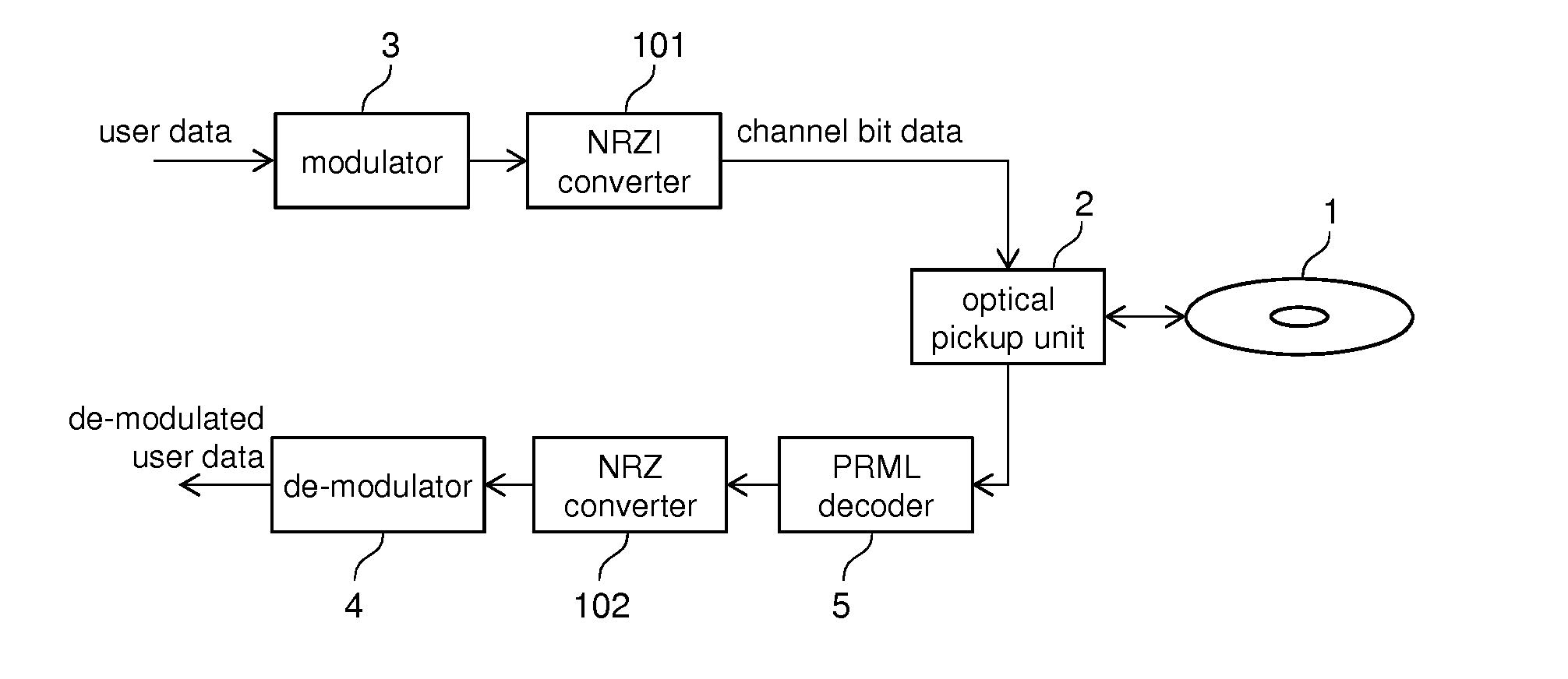
[0114]FIG. 20 is a configuration diagram of an optical disc device 100 according to an embodiment 3 of the present invention. The optical disc 1 is rotated by a spindle motor 152. An optical pickup 151 is configured by a light source used for recording and reproducing, an optical system such as an objective lens, and the like. The optical pickup 151 performs seek operation using a slider 153. A main circuit 154 instructs seek, rotation of the spindle motor, and the like. The main circuit 154 equips each of the circuits performing code modulation and demodulation described in the preceding embodiments (the channel bit processor 1900, the PRML decoder 70), a decode signal processing circuit, a processing system such as focusing and tracking feedback controller, a microprocessor, a memory, and the like. A firmware 155 controls the overall operation of the optical disc device 100. The firmware 155 is stored in a memory in the main circuit 154. The microprocessor executes it.

[0115]The pr...


PUM


Abstract

It is an objective of the present invention to provide a technique to balance DSV in channel bit word when using fixed-length run length limited code based on enumeration. A channel bit word processor according to the present invention: evaluates DSV of a channel bit word in NRZI format which is generated on the basis of enumeration; and selects a connection word which causes a minimum absolute value of DSV after connecting a plurality of channel bit words (refer to FIG. 15).

Description

CLAIM OF PRIORITY[0001]The present application claims priority from Japanese patent application JP 2014-152209 filed on Jul. 25, 2014, the content of which is hereby incorporated by reference into this application.BACKGROUND[0002]1. Technical Field[0003]The present invention relates to a technique for recording information using light.[0004]2. Background Art[0005]Parts of technical terms in following descriptions are those used in Blu-ray Disc (BD). These terms are sometimes referred to as other words in systems other than BD. However, since those skilled in the art could readily understand such words, technical terms in BD system will be used below.[0006]Storage capacities of optical discs have been expanded mainly by reducing wavelength of light sources, by increasing numerical apertures (NA) of objective lenses, and by increasing the number of recording layers per one disc. In dual layer BD systems, recording capacity of 50 GB have been achieved using blue semiconductor lasers an...

Claims


Application Information

Patent Timeline
IPC IPC(8): G11B20/12
CPCG11B20/1217G11B20/10277G11B20/1403G11B20/1833G11B2020/1859
Inventor KIKUGAWA, ATSUSHI
Owner HITACHI-LG DATA STORAGE
Why Eureka
Try Eureka