Rotation-independent helical antenna

a helical antenna, rotation-independent technology, applied in the direction of antennas, non-resonant long antennas, electrically long antennas, etc., can solve the problems of adversely affecting the performance of antennas, not being able to freely spin about the axis, time-consuming and one-rou, etc., to achieve the effect of improving the axial ratio

Active Publication Date: 2007-10-23
LOCKHEED MARTIN CORP
View PDF7 Cites 133 Cited by
  • Summary
  • Abstract
  • Description
  • Claims
  • Application Information

AI Technical Summary

Benefits of technology

[0010]The subject matter disclosed herein solves the above problems by providing a helical antenna that is relatively independent of rotation (e.g., “clocking” or “spinning”) about its central axis. That is, while the amplitude of a helical antenna is relatively independent of its rotation about its axis, such antennas are “clocked” (or rotated a...

Problems solved by technology

The feed line transfers radio-frequency (RF) energy from a transmitter to an antenna, and/or from an antenna to a receiver, but, if operating properly, the feed line typically does not radiate or intercept energy.
Consequently, once the antenna is located, for example within an array, it may not be freely spun about its axis without adversely impacting ant...

Method used


Image

  • Rotation-independent helical antenna
  • Rotation-independent helical antenna
  • Rotation-independent helical antenna

Examples


Embodiment Construction

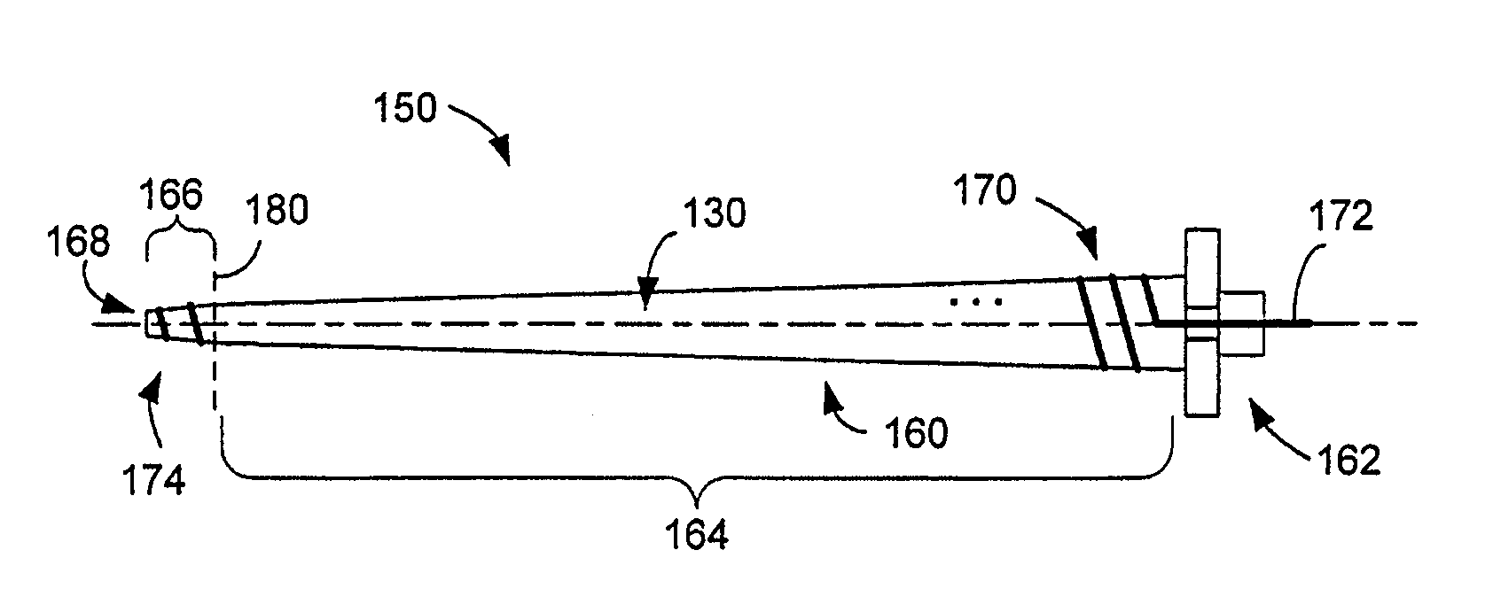
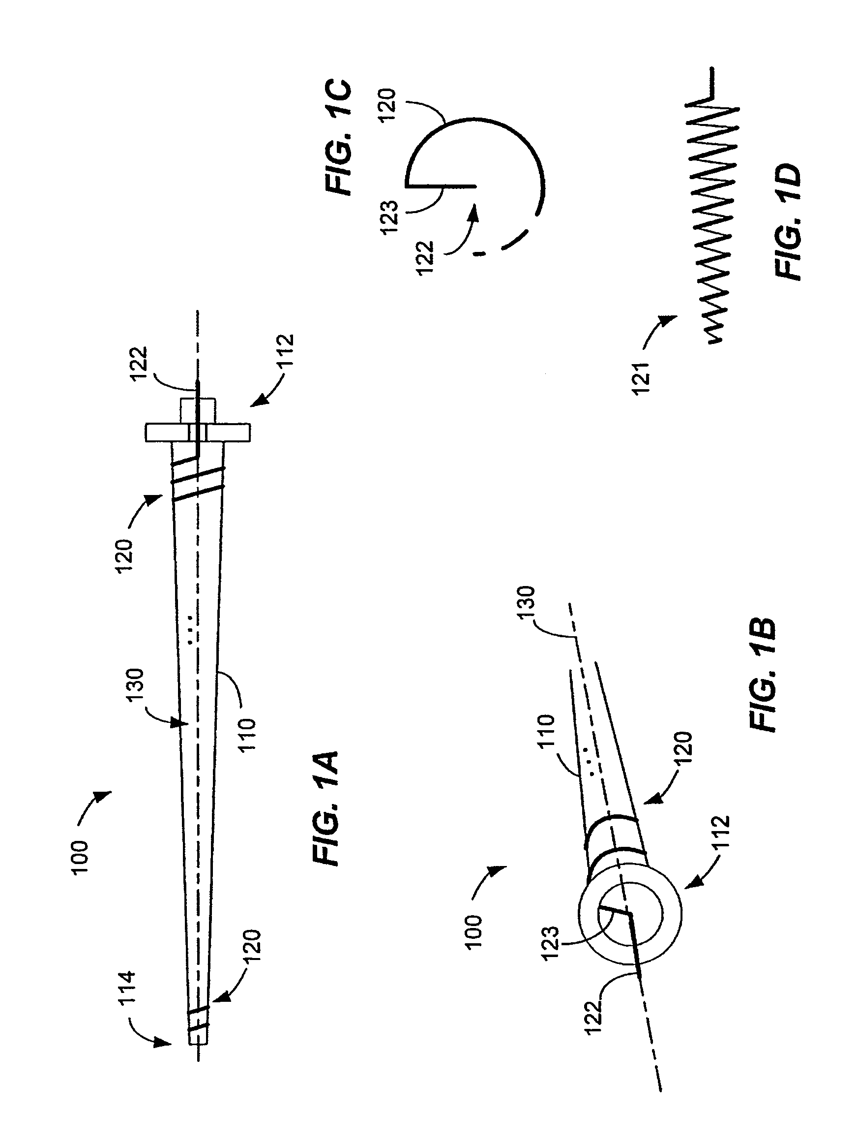
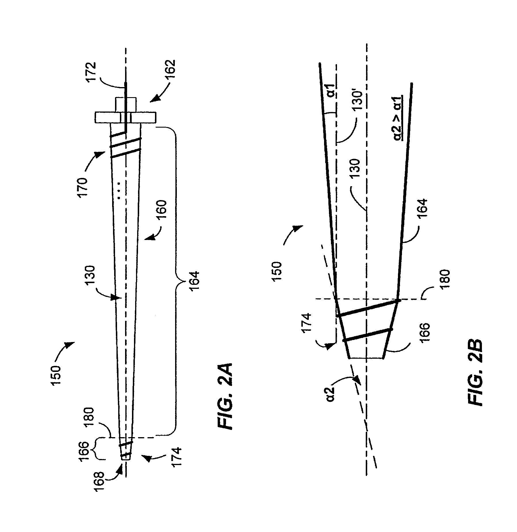
[0028]A helical antenna is provided that can be rotated or spun about its central axis (or “clocked”) to adjust its phase without requiring relocation of the antenna or components that couple to the antenna as a result of the clocking. Although, the phase changes with rotation, the amplitude of the antenna is substantially independent of its rotation about its central axis. The helical antenna includes an electrical conductor formed about the central axis, and includes a base end and a distal end. The rotational freedom of the antenna is accomplished by, for example, disposing or forming a feed line at the base end of the antenna and along the central axis. The feed line couples to a transmission path, through a ground plane, to allow signals to be provided to the coil for radiation or signals received by the coil to be provided to signal processing modules. The helical antenna may be a free standing helical coil, or the coil may be wound around a dielectric core, such as, for examp...


PUM


Abstract

A helical antenna having a central axis defined between a base end and a distal end comprises a helical conductor wound about the central axis and having a feed line disposed at the base end and along the central axis, and may also include an elongated dielectric core about which the electrical conductor is wound.

Description

STATEMENT AS TO RIGHTS TO INVENTIONS MADE UNDER FEDERALLY SPONSORED RESEARCH OR DEVELOPMENT[0001]Not Applicable.TECHNICAL FIELD[0002]This disclosure relates to phased antennas and, particularly, relates to helical antennas.BACKGROUND[0003]One form of antenna widely used for communication and radar purposes is a helical (or helix) antenna. A helical antenna is an antenna that emits or responds to electromagnetic (EM) fields in a circular polarization. Maximum radiation or response is wanted along the axis of the helix, about which the helical coil is disposed. A set of helical antennas may be mounted together to form an array, or phased array, antenna. In customary applications, the spacing in an array is larger than half of a wavelength.[0004]A helical antenna comprises an electrically conductive helical coil that can transmit or receive, or both, EM signals. The antenna properties of the helical coil are a function of several of its physical characteristics, including axial length,...

Claims


Application Information

Patent Timeline
IPC IPC(8): H01Q1/36
CPCH01Q1/362H01Q11/083H01Q11/08
Inventor LIER, ERIKLINDINGER, BERNARD F.SMOLENSKI, LEON R.
Owner LOCKHEED MARTIN CORP
Why Eureka
Try Eureka