

Controller/driver for driving display panel
a display panel and controller technology, applied in computing, instruments, electric digital data processing, etc., can solve the problems of inconvenient placement of controller/drivers and display panels within portable devices, undesirable controller/drivers within portable devices, and conventional color reduction based on dithering and error diffusion does not meet the requirements of such users, and achieves reduced display memory capacity and high quality images.
- Summary
- Abstract
- Description
- Claims
- Application Information
AI Technical Summary
Benefits of technology
Problems solved by technology
Method used
Image

Examples
first embodiment
1. Display Device Structure
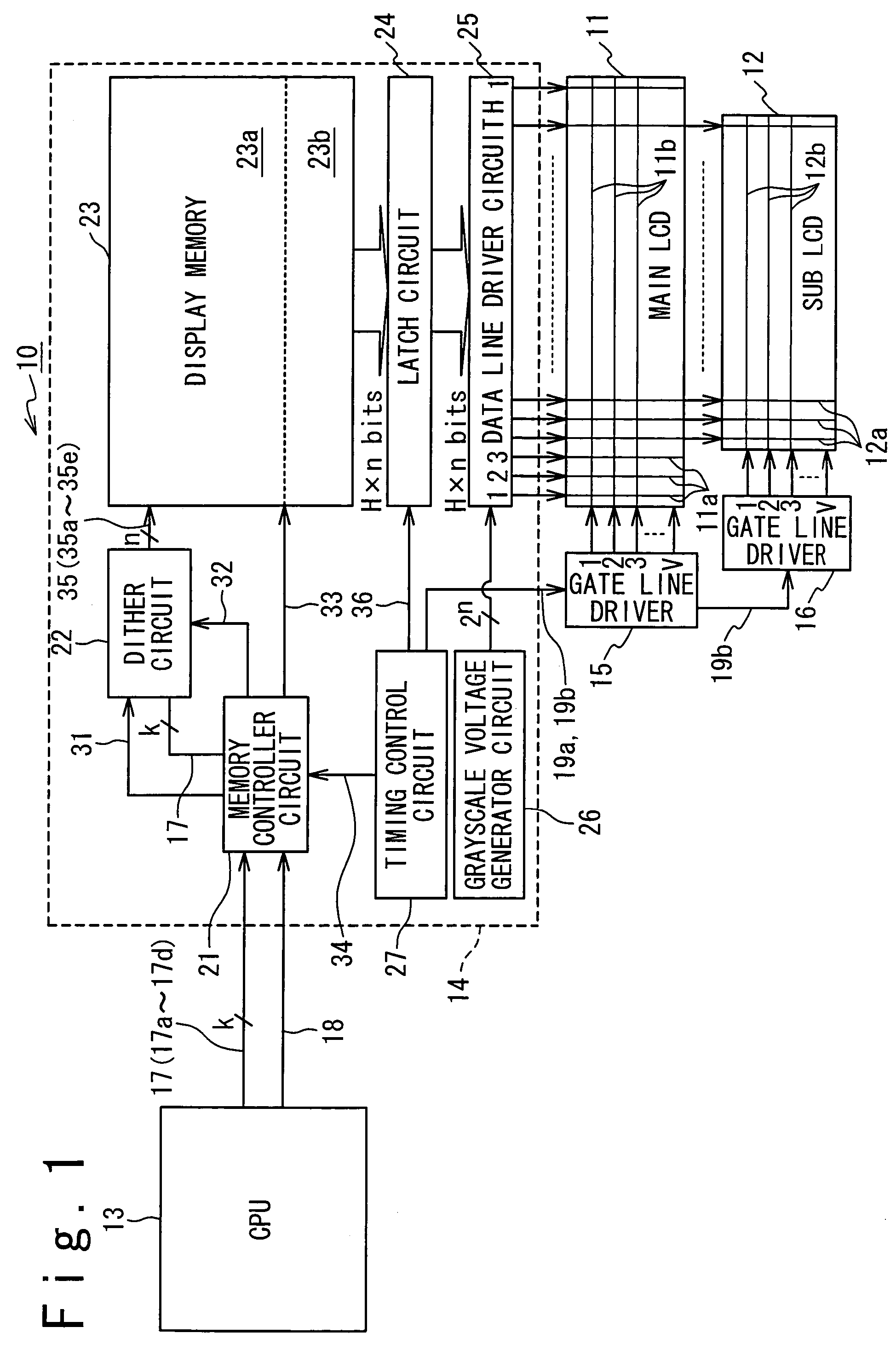
[0034]FIG. 1 is a block diagram illustrating an exemplary structure of a display device 10 in a first embodiment. The display device 10 is composed of a main LCD panel 11, a sub LCD panel 12, a CPU (central processing unit) 13, a controller / driver 14, and a pair of gate line drivers 15 and 16.
[0035]The main LCD panel 11 is composed of H1 data lines 11a disposed to extend in the y-axis direction (the vertical direction), and V1 gate lines 11b disposed to extend in the x-axis direction (the horizontal direction); it should be noted that H1 designates the number of the data lines 11a, and V1 designates the number of the gate lines 11b. Pixels are disposed at the respective intersections of the data lines 11a and the gate lines 11b. In other words, the main LCD panel 11 includes pixels arranged in V1 rows and H1 columns.
[0036]Correspondingly, the sub LCD panel 12 is composed of H2 data lines 12a disposed to extend in the y-axis direction, and V2 gate lines 12b...
second embodiment
1. Display Device Structure
[0079]FIG. 5 is a block diagram illustrating the structure of a display device 20 in accordance with a second embodiment of the present invention. The display device 20 offers the r-bit color reduction for the input image data 17 through error diffusion in place of dithering. In order to achieve error diffusion, the dither circuit 22 is replaced with an error diffusion circuit 28 in this embodiment. Additionally, the memory controller 21 is designed to provide an initial error switch signal 37 for the error diffusion circuit 28 in place of the matrix switch signal 28. The initial error switch signal 37 is indicative of the initial error to be used by the error diffusion circuit 28. Furthermore, the memory controller 21 is designed to provide the error diffusion circuit 28 with the coordinate data 31, representative of the x and y coordinates of each pixel.
[0080]FIG. 6 illustrates an exemplary structure of the error diffusion circuit 28, designed to offer 2...
third embodiment
1. Display Device Structure
[0094]FIG. 7 illustrates an exemplary structure of a display device 30 in accordance with a third embodiment of the present invention. In the third embodiment, image data is partially transmitted to a controller / driver in a vector form, and the remainder is transmitted in the bitmap form. Such method is effective for reducing the amount of image data transmitted to the controller / driver with the necessary image quality achieved. From the inventors' recognitions, the bitmap form is suitable for representing some images displayed on portable devices, and vector forms are suitable for representing other images.
[0095]Photograph images, which require many graylevels for achieving rich representations, such as fine gradation, are suitable for being represented in the bitmap form. Images mainly represented by contrast, such as video game images and map images, are not suitable for the bitmap form, because the use of the bitmap form unnecessarily increases the dat...
PUM
| Property | Measurement | Unit |
|---|---|---|
| color | aaaaa | aaaaa |
| color- | aaaaa | aaaaa |
| reduction | aaaaa | aaaaa |
Abstract
Description
Claims
Application Information