De-interlacing of video data

a video data and interlace technology, applied in the field of deinterlacing video data, can solve the problems of high risk of generating noisy frames and ineffective use of sequence data from adjacent fields, and achieve the effect of reducing the amount of artefacts related

Inactive Publication Date: 2008-02-26
IMAGINATION TECH LTD
View PDF31 Cites 10 Cited by
  • Summary
  • Abstract
  • Description
  • Claims
  • Application Information

AI Technical Summary

Benefits of technology

[0010]In finding the average the algorithm also performs a check on the vertical correlation of all the computed averages. If the correlation is not sufficiently high the average value is discarded. If no suitable average is found (no average passes the test), the new pixel is computed as a (potentially mathematically different) average between the pixels directly above and below. The above procedure is intended to minimize the artefacts related to a poor vertical correlation of the reconstructing pixels with respect to the other ones.

Problems solved by technology

In such cases, it may not be effective to use sequence data from adjacent fields, as they could be completely uncorrelated in time.
In particular, when reconstructing borders in a fast motion sequence of a detailed scene there is a high risk of generating a noisy frame as a result of the incorrect information coming from the edge detection part of the procedure.

Method used


Image

  • De-interlacing of video data
  • De-interlacing of video data
  • De-interlacing of video data

Examples


Embodiment Construction

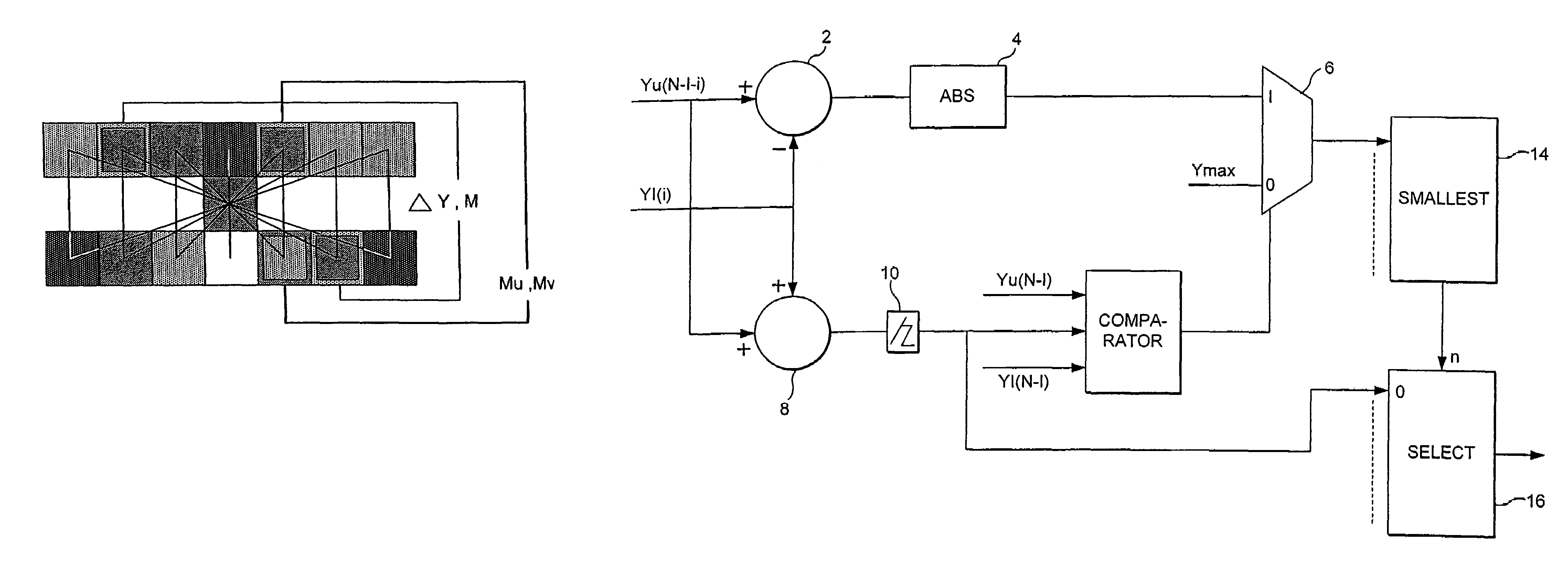
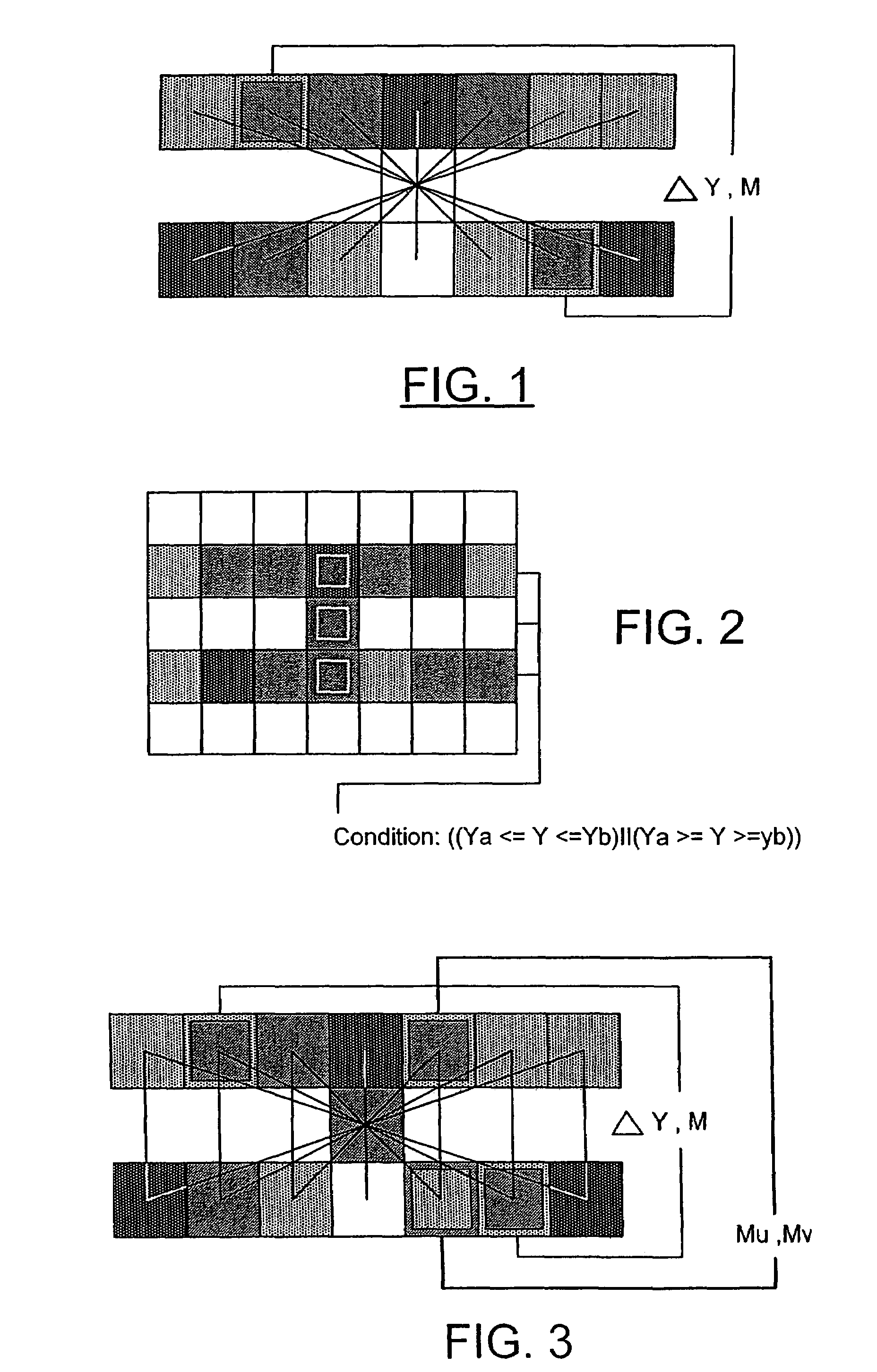
[0017]FIG. 1 shows how pixels are selected to compute the averages and differences between pixels in a single frame. The differences and the averages are computed along the imaginary lines connecting two pixels symmetrically opposite with respect to the pixels to be reconstructed. Every average is tested against the values of the pixels above and below the pixels to be reconstructed as shown in FIG. 1 and only the ones passing the test are subject to further processing. When the set of vertically correlated averages have been fully populated, the one corresponding to the best match for the pixels to be reconstructed is selected.

[0018]The procedure is performed as follows:

[0019]Stage a.

[0020]With reference to the FIG. 1, differences in colour (RGB model) between pairs of pixels coupled by the imaginary lines are computed. These pixels both come from the same field in an interlaced image.

Dk=((Pi.R−Pj.R)*(Pi.R−Pj.R)+(Pi.G−Pj.G)*(Pi.G−Pj.G)+(Pi.B−Pj.B)*(Pi.B−Pj.B)).

[0021]Where Dk is the...


PUM


Abstract

A method and apparatus are provided for deriving a progressive scan image from an interlaced image. In this, for each pixel to be inserted in the field from the interlaced image a difference value is derived from each pair of a set of symmetrically opposed pixels with respect to the pixel to be reconstructed and from adjacent lines to the pixel to be reconstructed. A determination is made as to which pair of pixels has the lowest difference value associated with it and the average value of this pixel is selected as a value of the pixel to be inserted.

Description

CROSS REFERENCE TO RELATED APPLICATION[0001]This application is a continuation of U.S. Ser. No. 10 / 600 246, filed Jun. 20, 2003 now abandoned.[0002]The present invention relates to a method and apparatus for increasing the resolution of a video image of the type that is particularly useful for TV signals (and, in general, any field based image transmission) when it is necessary to reconstruct missing information.BACKGROUND OF THE INVENTION[0003]Television and video images are typically displayed using a 2:1 interlace system. Resolution can be increased by converting the interlaced image to a 1:1 progressive scan image in which each field is applied to all the display lines instead of to alternate display lines.[0004]A known conversion technique is described in EP-A-0192292. In this, pixels in three consecutive display lines from adjacent first and second 2:1 interlace fields are examined. A pair or pixels P and Q are selected from each of two different lines in the second field. The...

Claims


Application Information

Patent Timeline
Patent Type & Authority Patents(United States)
IPC IPC(8): H04N7/01H04N5/44
CPCH04N7/012
Inventor FAZZINI, PAOLO GUISEPPE
Owner IMAGINATION TECH LTD
Why Eureka
Try Eureka