
Hearing aid with improved magnetic reception during wireless communication

a wireless communication and hearing aid technology, applied in the field of hearing aids, can solve the problems of low power consumption of hearing aid circuitry, unusual interference, and interference of rf-transceiver of hearing aid, and achieve the effect of filtering out background nois

Active Publication Date: 2014-07-15
GN HEARING AS
View PDF5 Cites 2 Cited by
  • Summary
  • Abstract
  • Description
  • Claims
  • Application Information

AI Technical Summary

Benefits of technology

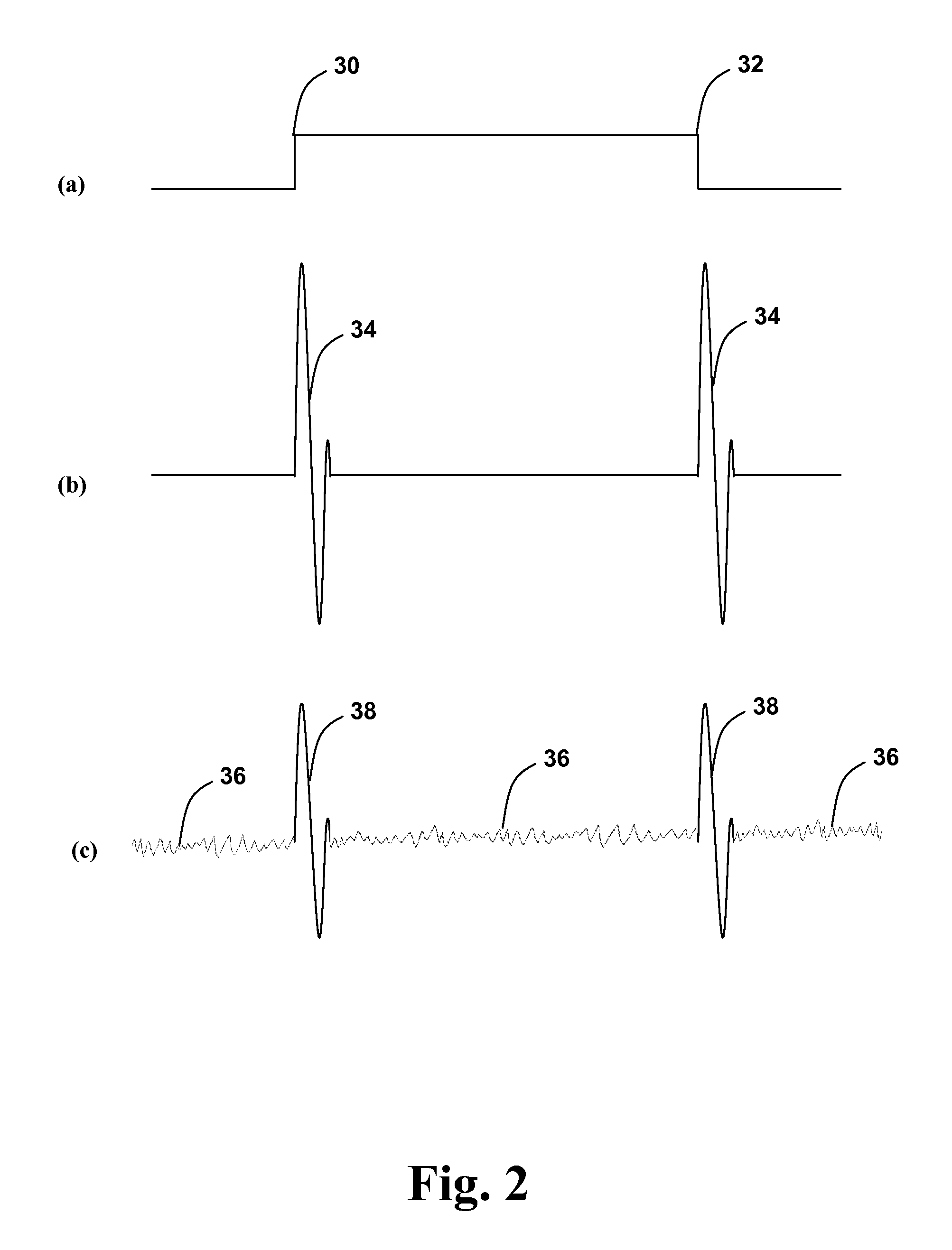
The patent describes a new hearing aid that prevents interference caused by the hearing aid's RF-transceiver. This interference can occur when the RF-transceiver is turned on or off, which can cause distortion in the hearing aid's output signal. The new hearing aid solves this problem by using an estimated output signal, based on parts of the output signal that have not been disturbed by the RF-transceiver. This estimate is weighted with a window to minimize the formation of artefacts in the auditory output signal. This innovation allows users to control the hearing aid with a remote and ensures proper signal transmission between the two hearing aids in a binaural hearing aid system.

Problems solved by technology

Although a telecoil constitutes a wide-band receiver, interference is unusual in most hearing loop situations.
In addition, an RF-transceiver of the hearing aid may also generate interference.
During normal operation, power consumption of hearing aid circuitry is very low.
Typically, an RF transceiver in a hearing aid consumes a comparatively large amount of power during transmission or reception.
The disturbing signal interferes with the desired signal in a disturbing and bothering way for the wearer of the hearing aid.
However, this way of solving the problem prevents the user of the hearing aid from using a remote control to adjust the hearing aid and also prevents transmission of signals to the other hearing aid in a binaural hearing aid system.

Method used


Image

  • Hearing aid with improved magnetic reception during wireless communication
  • Hearing aid with improved magnetic reception during wireless communication
  • Hearing aid with improved magnetic reception during wireless communication

Examples


Embodiment Construction

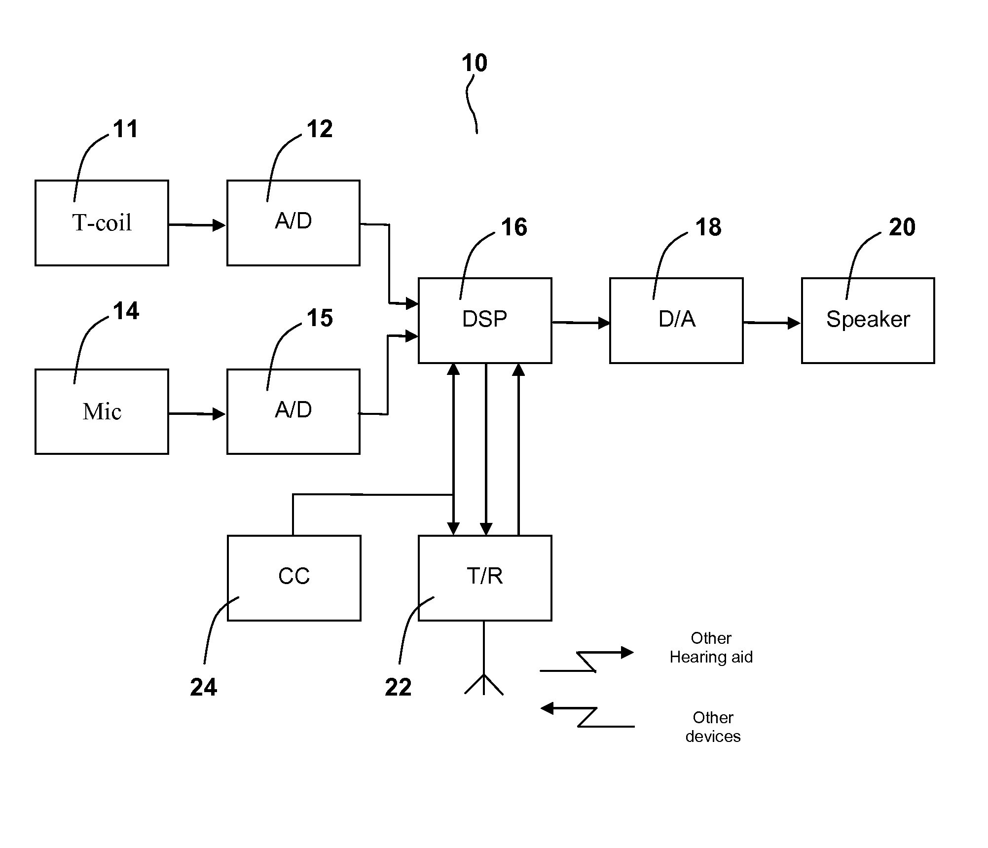
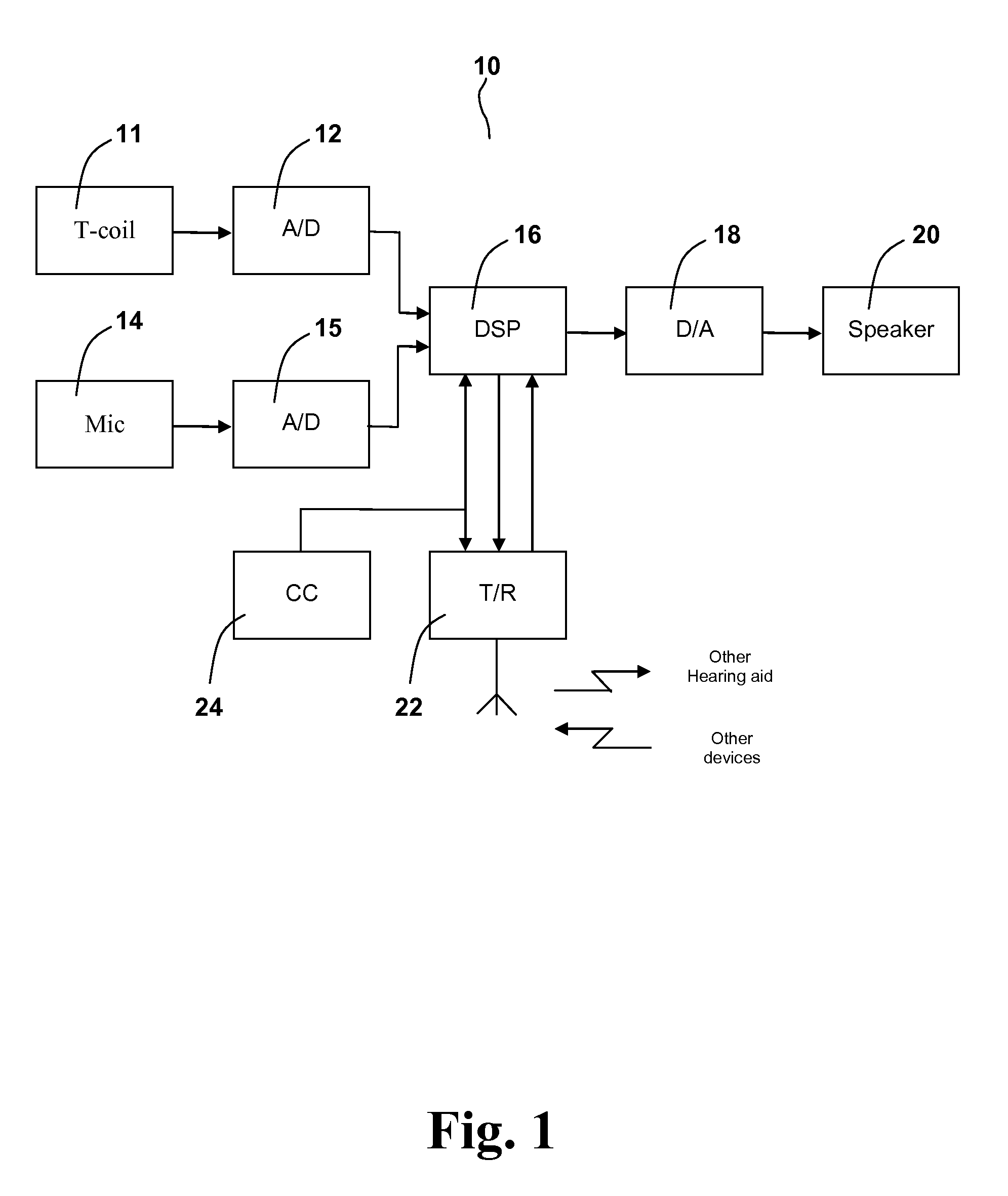
[0073]Various embodiments are described hereinafter with reference to the figures. It should also be noted that the figures are only intended to facilitate the description of the embodiments. They are not intended as an exhaustive description of the claimed invention or as a limitation on the scope of the claimed invention. In addition, an illustrated embodiment needs not have all the aspects or advantages shown. An aspect or an advantage described in conjunction with a particular embodiment is not necessarily limited to that embodiment and can be practiced in any other embodiments even if not so illustrated. The new hearing aid will now be described more fully hereinafter with reference to the accompanying drawings, in which various examples are shown. The appended patent claims may be embodied in different forms not shown in the accompanying drawings and should not be construed as limited to the examples set forth herein.

[0074]FIG. 1 is a simplified block diagram of an exemplary n...


PUM


Abstract

A hearing aid includes a magnetically sensitive transducer for conversion of a varying magnetic field into an audio signal, a processor configured to generate a hearing loss compensated output signal based on the audio signal, an output transducer for providing an auditory output signal based on the hearing loss compensated output signal, an RF transceiver for wireless communication, and a communication controller that is configured to turn the RF transceiver on and off, wherein the processor is further configured to generate the hearing loss compensated output signal based on an estimate of the audio signal within a time period comprising an event that the RF transceiver changes state between on and off, and wherein the estimate is based at least on a part of the audio signal input to the processor outside the time period.

Description

RELATED APPLICATION DATA[0001]This application claims priority to and the benefit of Danish Patent Application No. PA 2011 70720, filed on Dec. 16, 2011, pending, and EP Application No. EP 11194017, filed on Dec. 16, 2011, pending, the entire disclosure of which is expressly incorporated by reference herein.FIELD AND BACKGROUND[0002]The present application relates to a hearing aid with a telecoil, or another magnetically sensitive transducer, and an RF transceiver for wireless communication, e.g. via a wireless network, such as for wireless interconnection of two hearing aids in a binaural hearing aid system, and wireless interconnection of hearing aids with other devices, such as a remote control for a hearing aid, a fitting instrument, a mobile phone, a headset, a door bell, an alarm system, a broadcast system, etc, etc.SUMMARY[0003]Magnetic pick-up coils, often referred to as telecoils or T-coils (from “Telephone Coils”), in hearing aids allow audio sources to be electro-magnetic...

Claims


Application Information

Patent Timeline
Patent Type & Authority Patents(United States)
IPC IPC(8): H04R25/00
CPCH04R25/554H04R25/43H04R25/552H04R2225/49
Inventor PEDERSEN, BRIAN DAMNIJSSE, GERARD
Owner GN HEARING AS
Learn More