Neurostimulation Artefact Minimisation

Pending Publication Date: 2021-12-23
SALUDA MEDICAL
View PDF0 Cites 2 Cited by
  • Summary
  • Abstract
  • Description
  • Claims
  • Application Information

AI Technical Summary

Benefits of technology

The present invention is about improving the design of stimulation patterns for spinal cord stimulation and other neuromodulation methods. It provides techniques for reducing or nulling artifacts that can interfere with measuring tissue responses to stimulation. This is accomplished by delivering a set of stimuli with varying stimulation ratios and observing the resulting artifact to find the ratio that produces the least interference with the measurement. Additionally, the invention includes a method for configuring a passive electrode to reduce artifacts caused by the measurement electrode.

Problems solved by technology

However, this can be a difficult task as an observed CAP signal will typically have a maximum amplitude of a few tens of microvolts or less, whereas a stimulus applied to evoke the CAP is typically several volts.
Electrode artefact usually results from the stimulus, and manifests as a decaying output of several millivolts or hundreds of microvolts throughout the time that the CAP occurs, presenting a significant obstacle to isolating the much smaller CAP of interest.
As the neural response can be contemporaneous with the stimulus and / or the stimulus artefact, CAP measurements present a difficult challenge of implant design.
In practice, many non-ideal aspects of a circuit lead to artefact, and as these mostly have a decaying exponential characteristic which can be of either positive or negative polarity, identification and elimination of sources of artefact can be laborious.
However, to characterize responses evoked by a single implant such as responses from the dorsal columns to SCS, for example, high stimulation currents and close proximity between electrodes are required, and therefore the measurement process must overcome contemporaneous artefact directly, greatly exacerbating the difficulty of neural measurement.
Artefact remains a significant obstacle to measurement of neural responses proximal to the stimulus location, with the consequence that most if not all conventional neurostimulation implants, which are necessarily compact devices, do not take any measurements whatsoever of neural responses evoked by the implant's stimuli.

Method used


Image

  • Neurostimulation Artefact Minimisation
  • Neurostimulation Artefact Minimisation
  • Neurostimulation Artefact Minimisation

Examples


Embodiment Construction

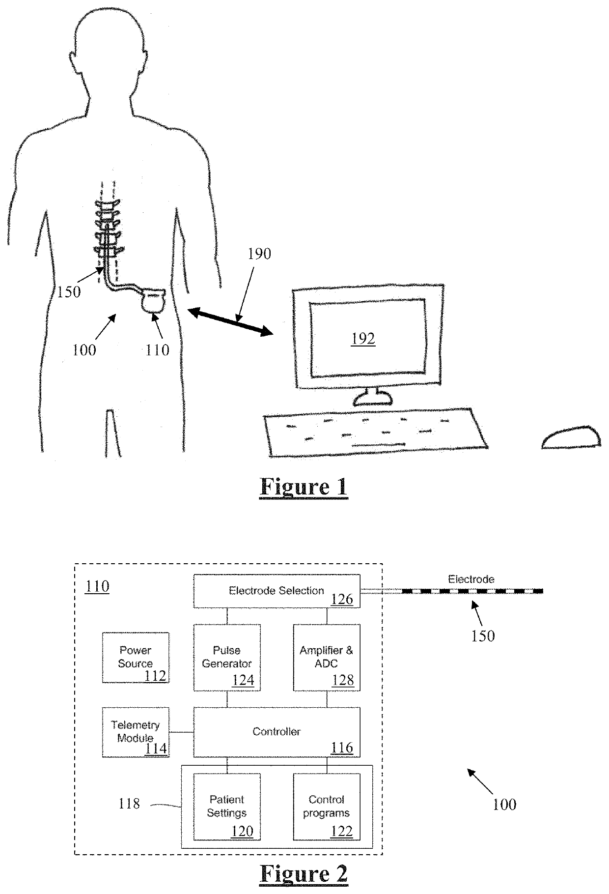
[0093]FIG. 1 schematically illustrates an implanted spinal cord stimulator 100. Stimulator 100 comprises an electronics module 110 implanted at a suitable location in the patient's lower abdominal area or posterior superior gluteal region, and an electrode assembly 150 implanted within the epidural space and connected to the module 110 by a suitable lead. Numerous aspects of operation of implanted neural device 100 are reconfigurable by an external control device 192. Moreover, implanted neural device 100 serves a data gathering role, with gathered data being communicated to external device 192 via any suitable transcutaneous communications channel 190.

[0094]FIG. 2 is a block diagram of the implanted neurostimulator 100. Module 110 contains a battery 112 and a telemetry module 114. In embodiments of the present invention, any suitable type of transcutaneous communication 190, such as infrared (IR), electromagnetic, capacitive and inductive transfer, may be used by telemetry module 1...


PUM


Abstract

A neurostimulation device has a stimulus, and a position of a measurement electrode relative to the stimulus, configured such that in artefact as arising relative to distance from the stimulus electrode a minima region of the artefact is substantially co-located with the measurement electrode. Or, a ratio of the inter-electrode spacing to the electrode length is between 2 and 3.66. Or, an impedance is connected to a passive electrode and is configured to reduce artefact arising on the measurement electrode.

Description

CROSS-REFERENCE TO RELATED APPLICATIONS[0001]This application claims the benefit of Australian Provisional Patent Application No. 2018904012 filed 23 Oct. 2018, which is incorporated herein by reference.TECHNICAL FIELD[0002]The present invention relates to measurement of compound action potentials evoked by a neurostimulator, and in particular to the minimisation of artefact caused by application of an electrical stimulus.BACKGROUND OF THE INVENTION[0003]There are a range of situations in which it is desirable to apply neural stimuli in order to give rise to a compound action potential (CAP). For example, neuromodulation is used to treat a variety of disorders including chronic pain, Parkinson's disease, and migraine. A neuromodulation system applies an electrical pulse to tissue in order to generate a therapeutic effect. When used to relieve chronic pain, the electrical pulse is applied to the dorsal column (DC) of the spinal cord, referred to as spinal cord stimulation (SCS). Neur...

Claims


Application Information

Patent Timeline
IPC IPC(8): A61N1/36A61N1/05
CPCA61N1/36139A61N1/0551A61N1/36071A61N1/36125A61N1/36157A61B5/7217A61N1/025A61N1/08A61N1/3606A61B5/6877A61B5/293A61B5/375A61B5/388A61N1/36062A61B5/24A61B5/377A61N1/36164
Inventor SINGLE, PETER SCOTT VALLACKKARANTONIS, DEAN MICHAELSCOTT, JONATHAN BRERETON
Owner SALUDA MEDICAL
Why Eureka
Try Eureka