
Simple fixing frame for curtain wall

A fixed frame and curtain wall technology, applied in the direction of walls, building components, buildings, etc., can solve the problems of unsafe, extended, rusted curtain walls, and achieve the effect of simple installation process, exquisite structure, and reduced wear and tear.

Active Publication Date: 2016-05-11
宏发建设有限公司
View PDF7 Cites 0 Cited by
  • Summary
  • Abstract
  • Description
  • Claims
  • Application Information

AI Technical Summary

Problems solved by technology

[0002] Curtain wall, also known as architectural curtain wall, curtain wall, is a facade that is often used in modern buildings. It is generally composed of metal, glass, stone and artificial panels, and is installed on the outermost layer of the building; the curtain wall does not bear any structure. The load is only connected with the structural plate or column to bear the self-weight and resist the wind pressure; the traditional curtain wall is fixed by glue, tie rod or cable, etc., and the installation speed of these methods is slow; at the same time, with the aging of the glue, the glued curtain wall After a period of use, it is easy to degumming, and the curtain wall becomes unsafe; and the fixing method of tie rod or cable needs to punch holes in the bracket and the curtain wall panel, which destroys the firmness and integrity of the curtain wall panel; at the same time, With the prolongation of the use time, the position of the drilled hole will be aged and rusted after being exposed to the wind and the sun; the screws fixing the curtain wall are easy to fall off, posing a big safety hazard; at the same time, because the curtain wall will vibrate during use, the Vibration will also accelerate the falling off of screws, so the traditional curtain wall needs frequent maintenance during use

Method used


Image

  • Simple fixing frame for curtain wall
  • Simple fixing frame for curtain wall
  • Simple fixing frame for curtain wall

Examples


Embodiment

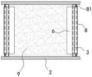
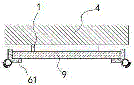
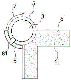
[0016] exist Figure 1 to Figure 4 In the shown embodiment, the simplified curtain wall fixing frame includes a push rod 1, a horizontal support plate 2 and a vertical shaft 3; The wall is vertical; the horizontal support plate 2 and the vertical shaft 3 are fixed on the periphery of the wall 4 and assembled into a rectangular grid; the vertical shaft 3 is sleeved with an adjustment drum 5; An L-shaped crimping plate 6 is fixed on the outer wall of the drum 5, and the axis of the crimping plate 6 is parallel to the vertical axis 3; There is a silica gel pad 61; an arc sheet 7 made of hard material is also fixed on the outer wall of the adjusting drum 5, and the axis of the arc sheet 7 coincides with the axis of the vertical shaft 3; A ratchet is provided on the arc piece 7; an arc lock 8 is installed on the outside of the adjusting drum 5, and the arc lock 8 is fixedly connected with the two ends of the vertical shaft 3 through a reinforcing rod 81; The arc length range of t...


PUM


Abstract

The invention relates to a simple fixing frame for a curtain wall. The simple fixing frame for the curtain wall comprises ejection rods, cross support plates and vertical shafts, wherein the cross support plates and the vertical shafts are fixed on the periphery of a wall body and are spliced in a rectangular net shape; each vertical shaft is sleeved by an adjusting rotating barrel, an L-shaped buckling plate is fixed on the outer barrel wall of the adjusting rotating barrel, the axis of the buckling plate is parallel to the vertical shaft, silica gel pads are attached to the plate surface, contacted with a curtain wall board, of the buckling plate, an arc sheet made of a hard material is fixed on the outer barrel wall of the adjusting rotating barrel, the axis of the arc sheet coincide with the axis of the vertical shaft, an arc lock is mounted outside the adjusting rotating barrel and fixedly connected with two ends of the vertical shaft through reinforcing rods, and a lock hole matched with the arc sheet is formed in the side wall of the arc lock. The fixing frame can mount the curtain wall board rapidly and firmly and has the advantages of long maintenance period, impact resistance, vibration resistance and the like.

Description

technical field [0001] The invention relates to a curtain wall fixing device, in particular to a curtain wall fixing frame. Background technique [0002] Curtain wall, also known as architectural curtain wall, curtain wall, is a facade that is often used in modern buildings. It is generally composed of metal, glass, stone and artificial panels, and is installed on the outermost layer of the building; the curtain wall does not bear any structure. The load is only connected with the structural plate or column to bear the self-weight and resist the wind pressure; the traditional curtain wall is fixed by glue, tie rod or cable, etc., and the installation speed of these methods is slow; at the same time, with the aging of the glue, the glued curtain wall After a period of use, it is easy to degumming, and the curtain wall becomes unsafe; and the fixing method of tie rod or cable needs to punch holes in the bracket and the curtain wall panel, which destroys the firmness and inte...

Claims


Application Information

Patent Timeline
Patent Type & Authority Applications(China)
IPC IPC(8): E04B2/88
Inventor 仲炳华
Owner 宏发建设有限公司
Learn More