
A vertical powder cooler

A cooler and powder technology, applied in the direction of direct contact heat exchanger, heat exchanger type, treatment of discharged materials, etc., can solve the problems of poor cooling effect, high energy consumption, and high probability of failure, and achieve installation and maintenance. The effect of convenience, lower production cost and simple structure

Active Publication Date: 2018-04-20
BEIJING NEW BUILDING MATERIALS PLC
View PDF16 Cites 0 Cited by
  • Summary
  • Abstract
  • Description
  • Claims
  • Application Information

AI Technical Summary

Problems solved by technology

For example, in the gypsum production process, the calcined plaster powder can reach about 150°C. If it enters the homogenization bin through related equipment without sufficient cooling, the accumulated heat may be too high in the bin. The powder will be calcined again, which will affect the clinker coagulation time and crystal water content and other indicators. In addition, in the process of conveying high-temperature clinker, excessive temperature will also have an adverse effect on related equipment.
[0003] At present, the commonly used cooling equipment is mainly divided into horizontal and vertical. For horizontal coolers, most of them are heavy in weight and high in power consumption, and the cooling space in the horizontal cavity structure is small, and the cooling effect is poor; for vertical coolers , there are often inappropriate feeding methods or ventilation methods. For example, for a certain swing-type flap discharge vertical cooler, the material needs to be discharged by the swing-type flap discharge device after cooling and dehumidification, which is different from this Compared with the reciprocating grid discharge device represented by the invention, the distribution of the blanking material and the flow of the cooling air are not uniform enough
Therefore, the material inside the cooler will agglomerate due to the uneven cooling and heat caused by the sudden cooling, which often leads to the occurrence of material blocking.
At the same time, the relatively complex structure often means that there is a high probability of failure during operation, which affects the operation of production
And most of the equipment also requires higher power due to complex structure, which in turn produces higher energy consumption

Method used


Image

  • A vertical powder cooler
  • A vertical powder cooler
  • A vertical powder cooler

Examples


Embodiment Construction

[0034] In order to make the purpose of the invention, technical solutions and beneficial effects of the present invention clearer, the embodiments of the present invention will be described below in conjunction with the accompanying drawings. The features in can be combined arbitrarily with each other.

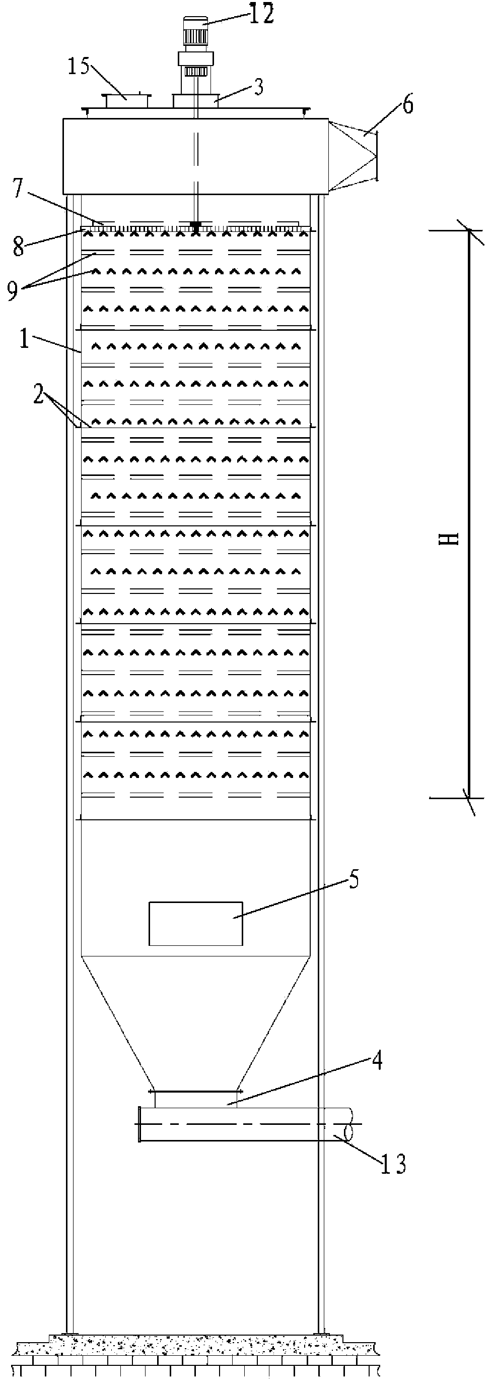
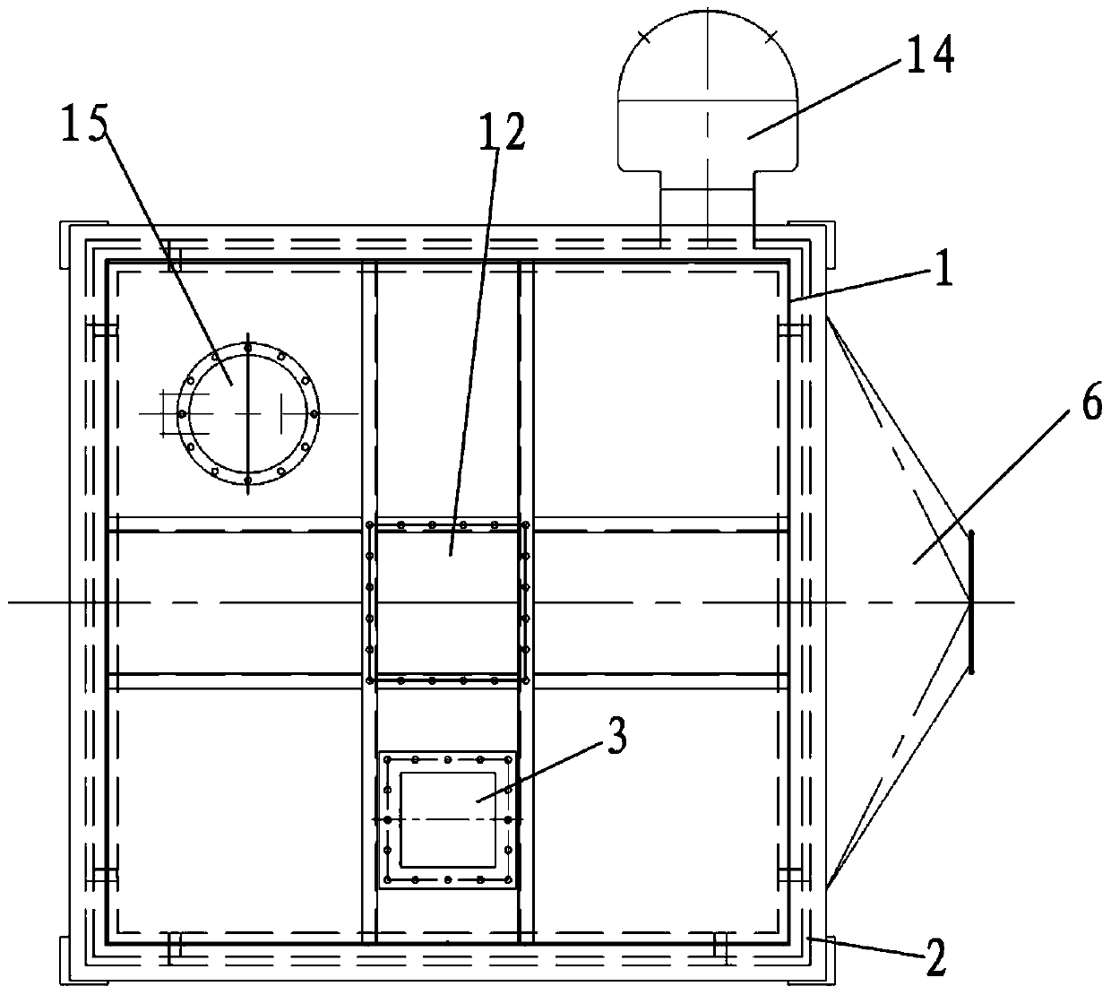
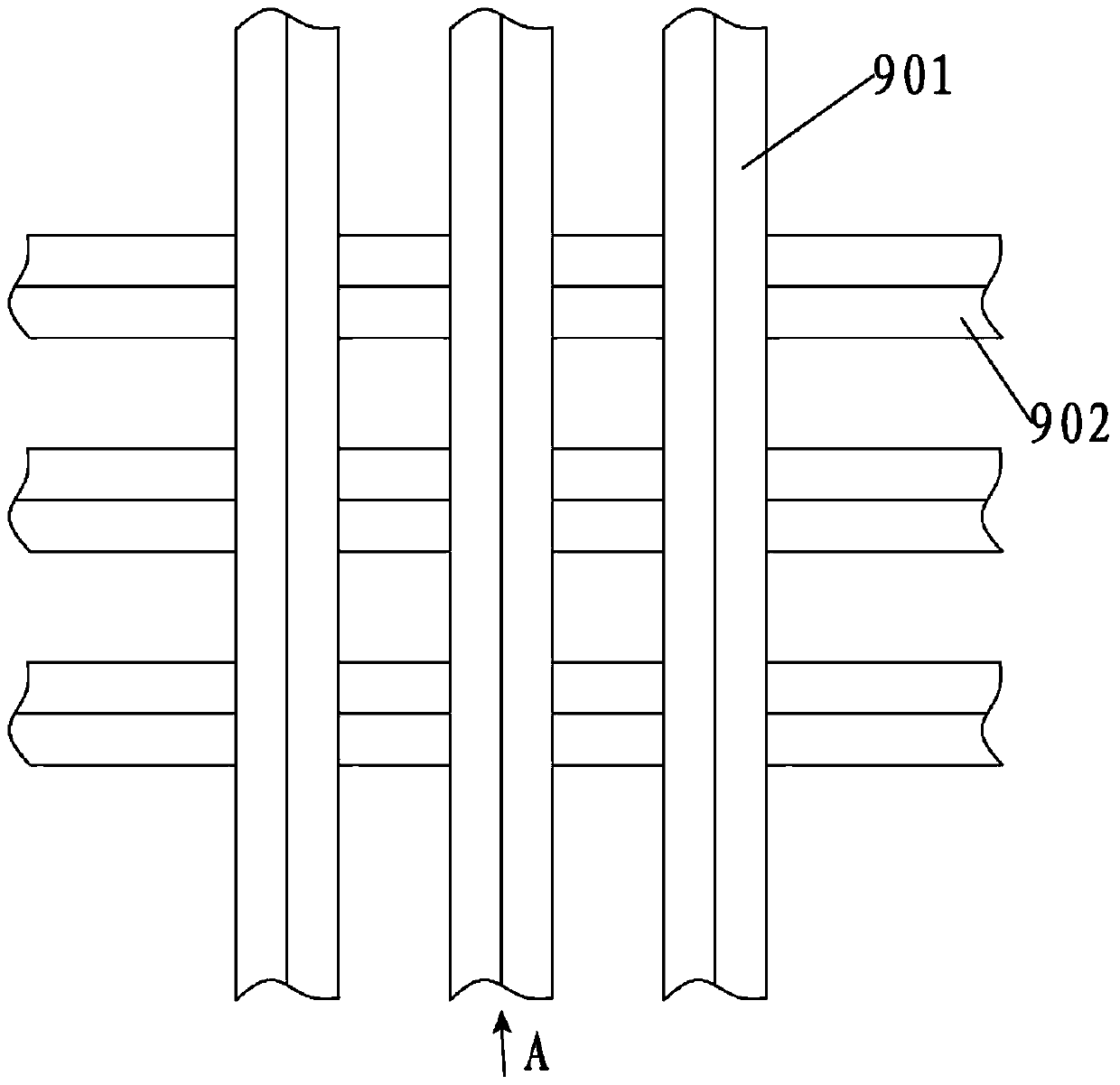
[0035] figure 1 A schematic diagram of the cooler structure. Such as figure 1 As shown, a vertical powder cooler includes a vertically arranged casing 1, the top of the casing 1 has a feed port 3, and the bottom has a discharge port 4, and also includes a blanking grate 8, a material puller 7 and distributor 9, the feeding grate 8 and the distributor 9 are arranged perpendicular to the falling direction of the material, the edge of the distributor 9 is fixed on the inner wall of the housing 1, and the feeding grate 8 is close to the feeding The port 3 is provided, and the material shifter 7 is above the blanking grate 8, and it communicates with the driving device 12 and th...


PUM


Abstract

A vertical powder cooler, comprising a shell, the top of the shell has a feed port, the bottom has a discharge port, and also includes a feeding grate, a feeder and a feeder, the feeding grate and The feeder is set perpendicular to the falling direction of the material, the edge of the feeder is fixed on the inner wall of the housing, the feeding grate is set close to the feeding port, the feeder is above the feeding grate, and after it communicates with the driving device Rotating, also includes air supply device for good cooling effect. The invention realizes the vertical transportation of the material while cooling the powder material, and has the advantages of simple structure, low energy consumption, good cooling effect and the like.

Description

technical field [0001] The invention relates to a cooler, in particular to a vertical cooler suitable for powder. Background technique [0002] Reducing the temperature of high-temperature materials is a very necessary process in many fields. For example, in the process of gypsum production, the calcined plaster powder can reach about 150°C. If it enters the homogenization bin through related equipment without sufficient cooling, the accumulated heat may be too high in the bin. The powder will be calcined again, which will affect the clinker coagulation time and crystal water content and other indicators. In addition, in the process of conveying high-temperature clinker, excessive temperature will also have an adverse effect on related equipment. [0003] At present, the commonly used cooling equipment is mainly divided into horizontal and vertical. For horizontal coolers, most of them are heavy in weight and high in power consumption, and the cooling space in the horizonta...

Claims


Application Information

Patent Timeline
Patent Type & Authority Patents(China)
IPC IPC(8): F28C3/14F27D15/02
Inventor 张羽飞刘明刚任有欢
Owner BEIJING NEW BUILDING MATERIALS PLC
Learn More