Polishing device for notebook computer surface cover plate
A technology for notebooks and cover plates, which is applied in the direction of grinding drive devices, grinding/polishing safety devices, grinding machines, etc., and can solve problems such as uneven grinding
- Summary
- Abstract
- Description
- Claims
- Application Information
AI Technical Summary
Problems solved by technology
Method used
Image
Examples
Embodiment 1
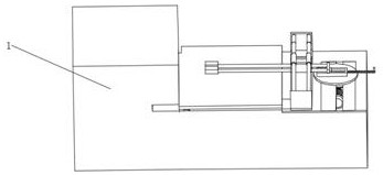
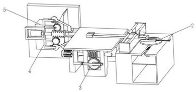
[0024] see figure 1 , figure 2 and image 3 , in an embodiment of the present invention, a polishing device for a notebook surface cover includes a box body 1, a polishing assembly 2 is provided on one side of the interior of the box body 1, and a moving assembly is provided on one side of the polishing assembly 2 3. One side of the moving component 3 is provided with a clamping component 4 , and one side of the clamping component 4 is provided with a dust suction component 5 .
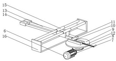
[0025] The grinding assembly 2 includes a servo motor A6, a bevel gear A7 is fixedly connected to the output end of the servo motor A6, a bevel gear B8 is meshed above the bevel gear A7, and a turntable 9 is fixedly connected above the bevel gear B8 , the top of the turntable 9 is fixedly connected with a chute, the inside of the chute is slidably connected with a slider 10, and the top of the slider 10 is rotatably connected with a fixed block A11, and the other side of the slider A10 is fixed A ...
Embodiment 2
[0027] Such as Figure 4 As shown, different from Embodiment 1, in another preferred mode provided by the present invention, the moving assembly 3 includes a fixed block B17, and the fixed block B17 is fixedly connected to one side wall of the box body 1, so that The inside of the fixed block B17 is slidably connected with an upper panel 18 through a chute, one side of the upper panel 18 is fitted with a worm 19, and the inside of the worm 19 is slidably connected with a rotating shaft 20, one of the rotating shafts 20 The side is fixedly connected with a servo motor B21, the servo motor B21 is fixedly connected with the fixed block B17, the bottom of the worm 19 is engaged with a worm wheel 22, and one side of the worm wheel 22 is connected with a rotating rod A23, and the rotating rod A23 The other side of the rotating rod B24 is connected to the rotating rod B24, and the other side of the rotating rod B24 is connected to the fixed block B17 in rotation, and the servo motor ...
Embodiment 3
[0029] Such as Figure 5 and Figure 6 As shown, different from Embodiment 2, in another preferred mode provided by the present invention, the clamping assembly 4 includes a bracket B25, one side of the bracket B25 is fixedly connected to the inner wall of the box body 1, and the The inside of the bracket B25 is fixedly connected with a hydraulic telescopic rod 26, one side of the hydraulic telescopic rod 26 runs through the bracket B25 and is fixedly connected with a tooth column 27, and the other side of the tooth column 27 is fixedly connected with a fixed piece 28, the The inside of the bracket B25 is rotatably connected with a gear 29, the gear 29 is meshed with the gear column 27, and the other side of the gear 29 is meshed with an incomplete gear 30, and the incomplete gear 30 is rotatably connected with the bracket B25. The incomplete gear 30 is fixedly connected with the same fixed piece 28, and the other side of the tooth column 27 is provided with the same gear 29,...
PUM
 Abstract
Description
Claims
Application Information
 - R&D
- Intellectual Property
- Life Sciences
- Materials
- Tech Scout
- Unparalleled Data Quality
- Higher Quality Content
- 60% Fewer Hallucinations
Browse by: Latest US Patents, China's latest patents, Technical Efficacy Thesaurus, Application Domain, Technology Topic, Popular Technical Reports.
© 2025 PatSnap. All rights reserved.Legal|Privacy policy|Modern Slavery Act Transparency Statement|Sitemap|About US| Contact US: help@patsnap.com


