Switch device

Active Publication Date: 2008-07-24
PANASONIC CORP
View PDF6 Cites 0 Cited by
  • Summary
  • Abstract
  • Description
  • Claims
  • Application Information

AI Technical Summary

Benefits of technology

[0016]The present invention provides a switch device that has greater resistance to pull-out of an operating body thereof and is easy to assemble.
[0017]For the switch device of the present invention, a U-shaped spring member is placed on the outer periphery of a hollow cylindrical part of the operating body that has the operating shaft of the switch inserted therein. Arm portions upwardly inwardly extending from both ends of the spring member are fitted into holes through the hollow cylindrical part and brought into resilient contact with a groove on the outer periphery of the operating shaft. The arm portions at both ends of the spring member are fitted into the groove on the operating shaft, so that the operating body is engaged by the operating shaft of the switch. This structure prevents pull-out of the operating body and ensures fastening thereof. Because the operating shaft is fastened in the hollow cylindrical part by yielding of the entire spring member, assembly thereof is easy.

Problems solved by technology

However, when operating body 1 and switch 2 are assembled, press-fitting operating shaft 2A into hollow cylindrical part 1A by hands is difficult and jigs are necessary for the assembly.
As described above, in the conventional switch device, increasing the fastening force of spring member 3 to prevent the pull-out of operating body 1 makes the assembly of operating body 1 and switch 2 difficult and necessitates more assembly time.

Method used


Image

  • Switch device
  • Switch device
  • Switch device

Examples


first exemplary embodiment

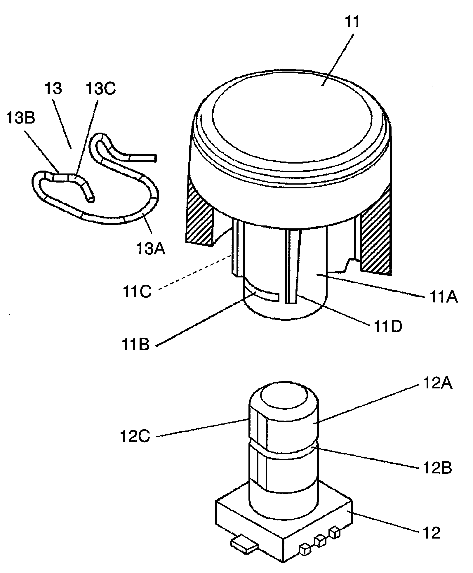
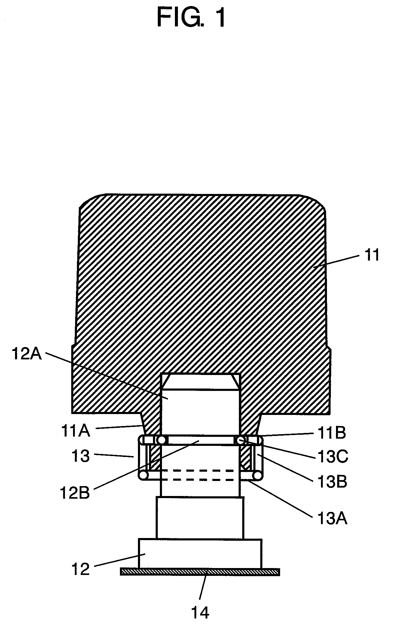
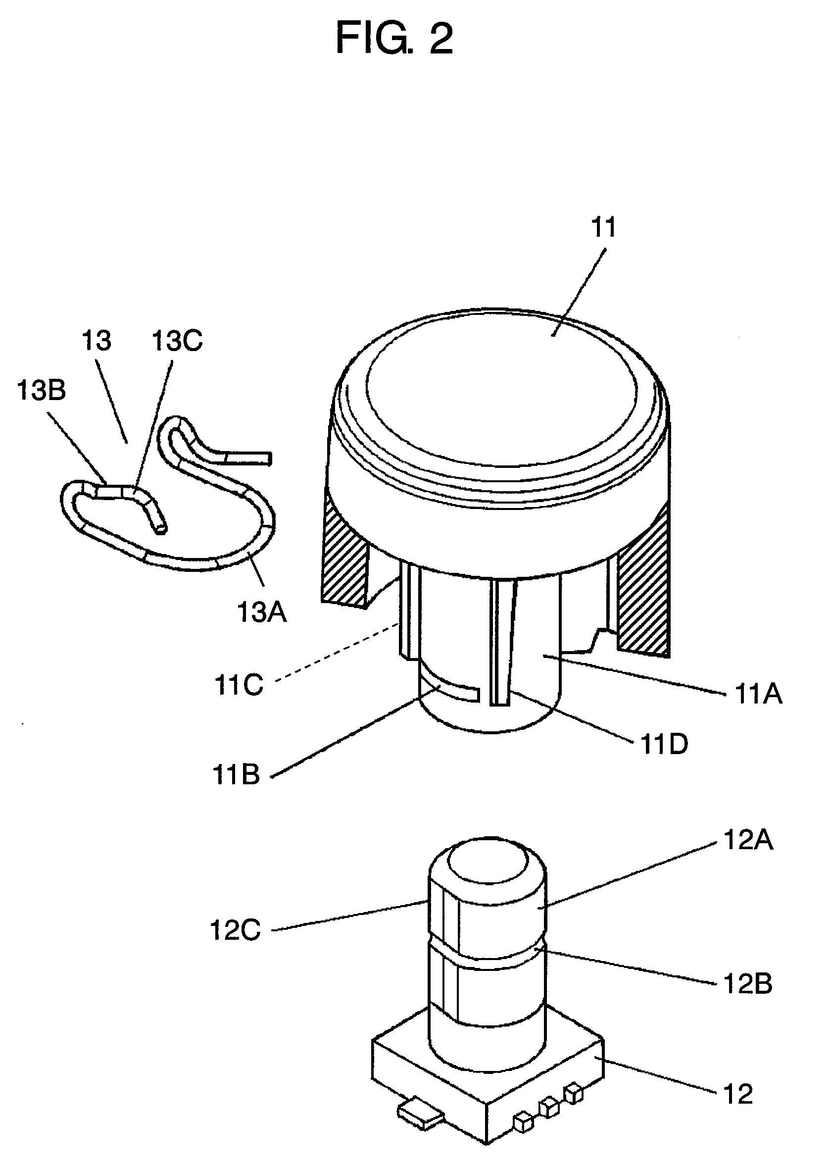
[0030]FIG. 1 is a sectional view of a switch device in accordance with the first exemplary embodiment of the present invention. FIG. 2 is an exploded perspective view partially in section of the switch device in accordance with the first exemplary embodiment. With reference to FIGS. 1 and 2, columnar operating body 11 is made of an insulating resin, such as acrylic and polycarbonate. On the bottom face of operating body 11, downwardly-projecting hollow cylindrical part 11A is formed. Provided on the outer periphery of hollow cylindrical part 11A are a plurality of facing holes 11B, flat part 11C, and a plurality of walls 11D formed above holes 11B.

[0031]Operating shaft 12A of switch 12 is columnar and projects upwardly. Formed in switch 12 are a plurality of switch contacts (not shown) to be brought into or out of contact with each other by rotation of operating shaft 12A. Groove 12B is formed on the outer periphery of operating shaft 12A. Flat part 12C is formed on the side face of...


PUM


Abstract

A U-shaped spring member is placed on the outer periphery of a hollow cylindrical part of an operating body. Engaging portions in arm portions upwardly inwardly extending from both ends of the spring member are fitted into holes through the hollow cylindrical part and brought into resilient contact with a groove on the outer periphery of an operating shaft. This structure provides a switch device that has great resistance to pull-out of the operating body for secure fastening thereof and is easy to assemble.

Description

BACKGROUND OF THE INVENTION[0001]1. Field of the Invention[0002]The present invention relates to a switch device to be mainly used to operate the air-conditioner or audio equipment for a vehicle.[0003]2. Background Art[0004]In recent years, an increasing number of vehicles have switch devices including a various kinds of operating bodies on the front panel in the vehicle cabin for the operation of various kinds of electronic devices, such as an air-conditioner and audio equipment.[0005]A description is provided of such a conventional switch device with reference to FIGS. 6 and 7.[0006]FIG. 6 is a sectional view of a conventional switch device. FIG. 7 is an exploded perspective view of the conventional switch device. With reference to FIGS. 6 and 7, downwardly-projecting hollow cylindrical part 1A is formed on the bottom face of columnar operating body 1 made of an insulating resin. On the outer periphery of hollow cylindrical part 1A, a plurality of notches 1B are provided.[0007]Ope...

Claims


Application Information

Patent Timeline
IPC IPC(8): H01H3/00
CPCH01H3/10
Inventor KISHIMOTO, TAKAYOSHI
Owner PANASONIC CORP
Why Eureka
Try Eureka