
Relayed communication with versatile self-interference cancellation
a communication and self-interference technology, applied in the field of radio frequency or optical communication system, can solve the problems of inability to fully realize the advantages of self-interference cancellation, inconvenient retrofitting of large number of existing systems, and high cost of retrofitting
- Summary
- Abstract
- Description
- Claims
- Application Information
AI Technical Summary
Benefits of technology
Problems solved by technology
Method used
Image

Examples
Embodiment Construction
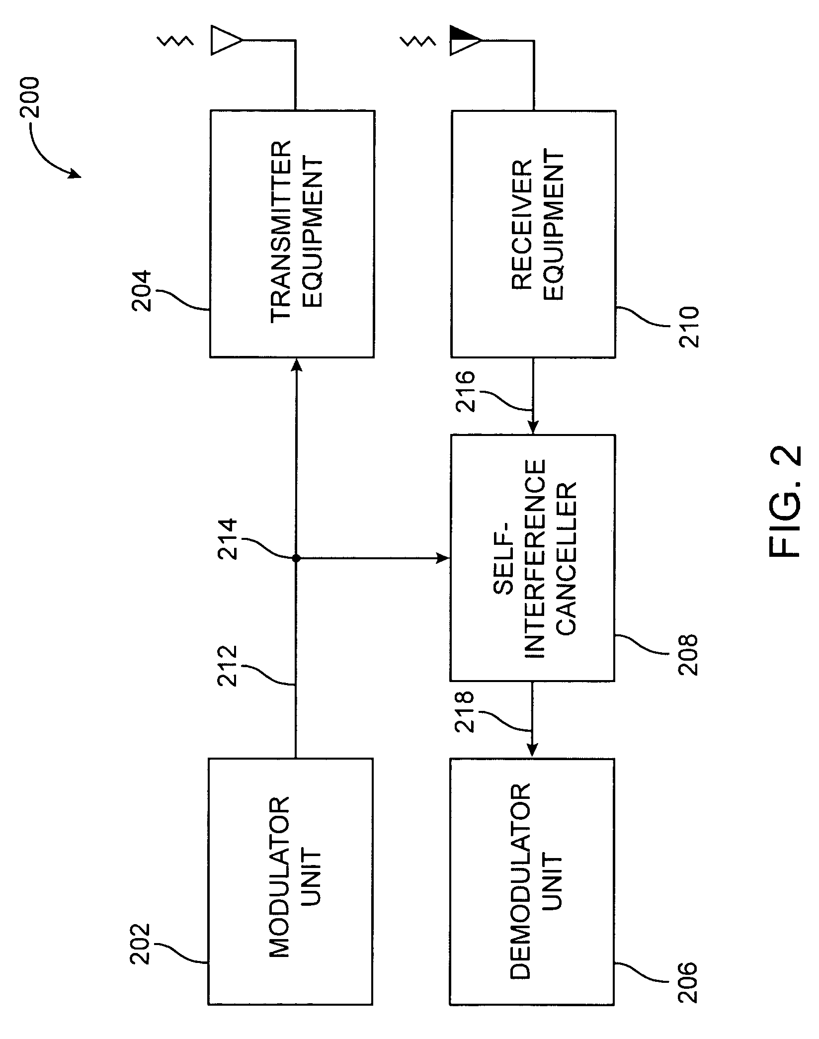
[0018]FIG. 2 illustrates an embodiment of a versatile self-interference cancellation system 200 of the present invention. The self-interference cancellation system 200 comprises a modulator unit 202, transmitter equipment 204, a demodulator unit 206, a self-interference canceler 208, and receiver equipment 210.
[0019]On the transmit side, the modulator unit 202 provides a TX interface signal 212 via an accessible feed line (typically coaxial) to the transmitter equipment 204. The TX interface signal 212 is a representation of the locally modulated signal which is also called the near signal. This representation is at or near an interface frequency that is not baseband. The transmitter equipment 204 can be any equipment along the transmit path, such as an upconverter, mixer, splitter, combiner, splitter / combiner, amplifier, antenna, or the like. A signal splitter 214 in the TX interface signal line allows the TX interface signal 212 to be easily tapped for purposes of self-interferenc...
PUM
 Abstract
Description
Claims
Application Information