
Apparatus and method for reducing self-interference in a radio system

a radio system and self-interference technology, applied in the field of full-duplex radio wireless systems and methods, can solve the problems of high cost, non-integration, and high cost of bulky devices, and achieve the effects of reducing the number of filters, and reducing the number of devices

Active Publication Date: 2013-07-30
HUAWEI TECH CO LTD
View PDF11 Cites 62 Cited by
  • Summary
  • Abstract
  • Description
  • Claims
  • Application Information

AI Technical Summary

Benefits of technology

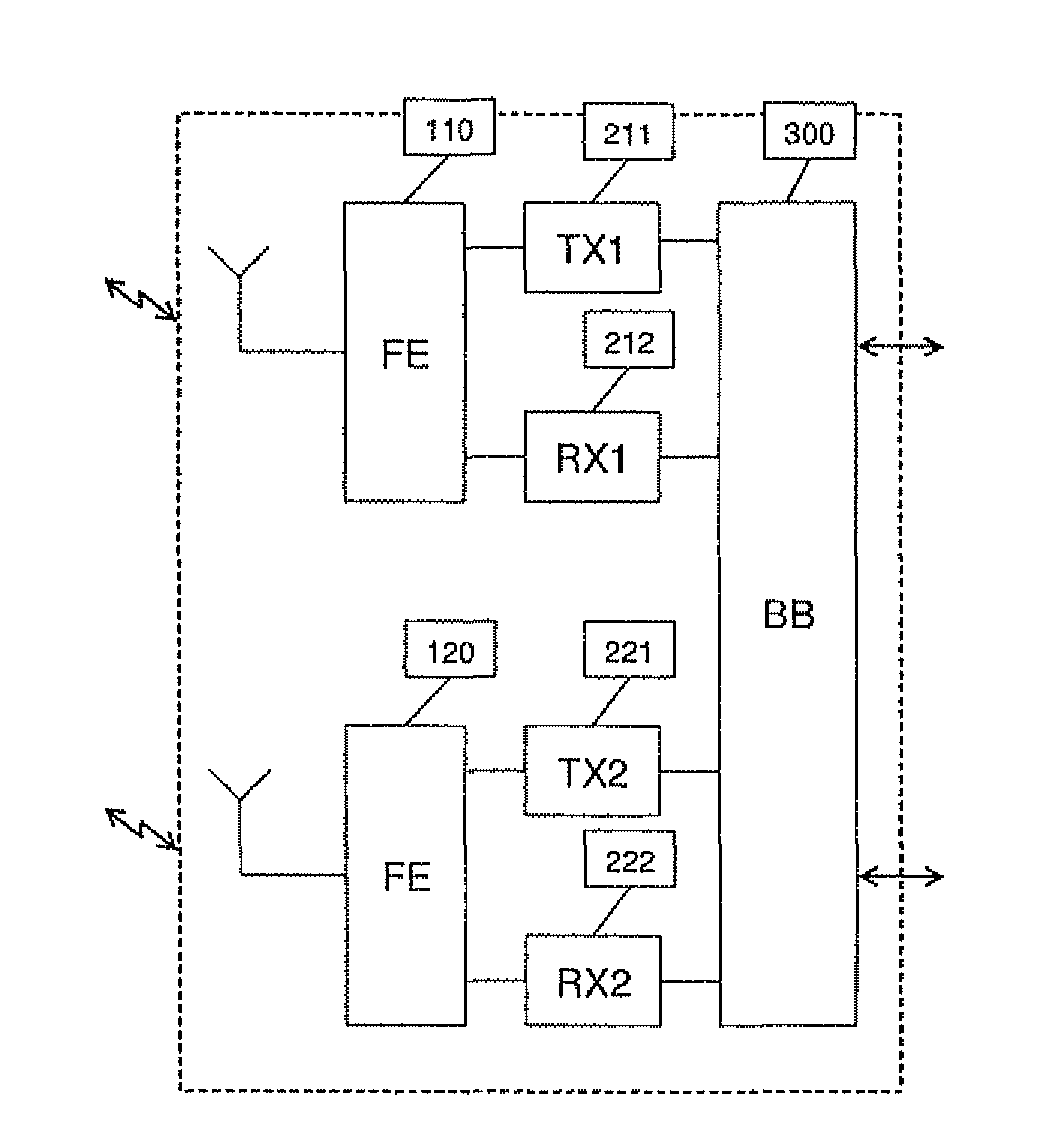
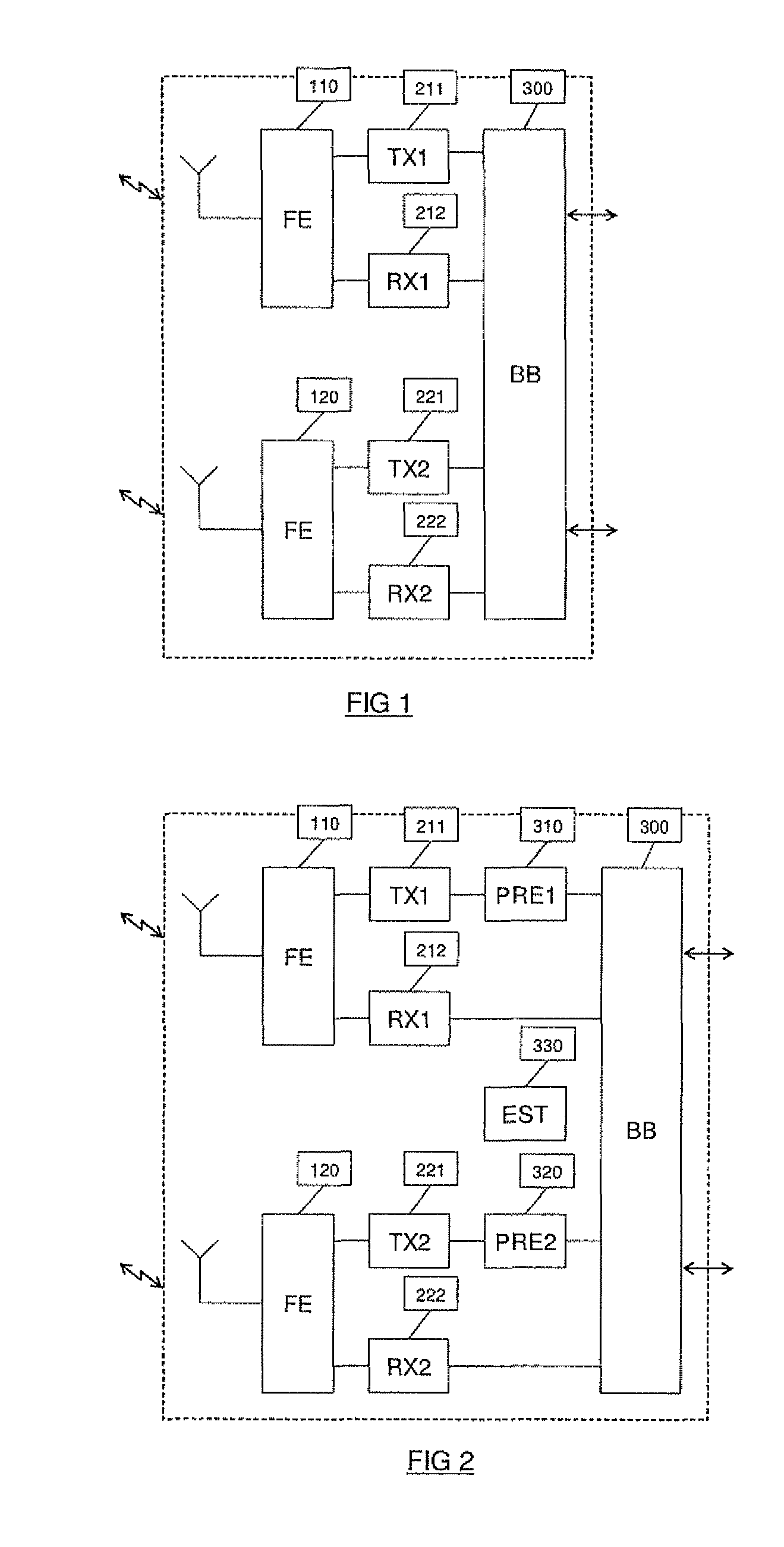
The present invention is about a new way to reduce self-interference in radio wireless communication systems. It uses multiple antennas and transmit chains to achieve a synergistic effect. The invention includes a self-interference suppression module (called a "precompensation circuit") which modifies the transmit signals to minimize the interference at the receiver inputs. This results in a more reliable and effective communication. The invention also includes a method for reducing self-interference during transmission. Overall, the invention improves the quality and reliability of wireless communication systems.

Problems solved by technology

However, a full duplex receiver is susceptible to a problem called “self-interference”.
Typically, full duplex transceivers resolve the self-interference problem by suppressing signals in the transmit frequency band at the receiver input, often requiring advanced, non-integrateable, expensive and bulky devices such as Surface Acoustic Wave (SAW) filters.
Clearly, with the continuous drive towards lower cost and smaller footprint, the problem of reducing self-interference is more pressing than ever.
Secondly, MIMO techniques have been introduced due to the radio wireless channel environment existing in a mobile communication system is subject to inevitable errors.
These can be due to several factors such as multipath interference, shadowing, propagation attenuation, time-varying noise, interference and fading, all of which result in a deterioration in the overall performance of the mobile communication system.
Of particular relevance is that the introduction of these techniques comes at a cost and footprint penalty, both very sensitive parameters in the modern communications systems transceivers.

Method used


Image

  • Apparatus and method for reducing self-interference in a radio system
  • Apparatus and method for reducing self-interference in a radio system
  • Apparatus and method for reducing self-interference in a radio system

Examples


Embodiment Construction

[0021]In the following detailed description of the preferred embodiments, reference is made to the accompanying drawings, which form a part hereof, and within which are shown by way of illustration specific embodiments by which the invention may be practiced. The drawings described are only schematic and are non-limiting. In the drawings, the size of some of the elements may be exaggerated and not drawn on scale for illustrative purposes. Those skilled in the art will recognize that other embodiments may be utilized and structural changes may be made without departing from the scope of the invention.

[0022]Furthermore, the terms first, second, third and the like in the description and in the claims, are used for distinguishing between similar elements and not necessarily for describing a sequential or chronological order. It is to be understood that the terms so used are interchangeable under appropriate circumstances and that the embodiments of the invention described herein are cap...


PUM


Abstract

Full duplex radio wireless systems and methods and especially transceivers for full duplex radio wireless systems with reduction of self-interference are described. MIMO (=multiple input multiple output several antennas for output and input) is used within one device with multiple antennas to remove self-interference in a proactive way. For example, a transceiver is described having self-interference suppression, comprising, within one transceiver device: two or more transmitters comprising one or more signal generators for transmitting transmit signals having transmit center frequencies in a selected first subchannel; and one or more receivers having receiver inputs for simultaneously receiving a desired receive signal in a second subchannel and an undesired accumulated interference signal due to said transmitted signals; and at least one of said transmitters also comprising a precompensation circuit that modifies the transmit signals such that said accumulated interference signal at the receiver(s) inputs is reduced.

Description

TECHNICAL FIELD OF THE INVENTION[0001]This invention relates generally to full duplex radio wireless systems and methods and especially to the design of transceivers for full duplex radio wireless systems with reduction of self-interference.BACKGROUND OF WE INVENTION[0002]A communication system can be full duplex or half duplex. In a full duplex system each communicating transceiver can receive and transmit signals simultaneously, typically in distinct frequency bands (frequency division) or by using different codes (code division) or combinations of these. In contrast, in a half duplex system each transceiver receives and transmits signals in separate time periods, typically within a single frequency band. The former approach has several advantages due to its relaxed need for time synchronization, its higher efficiency due to lack of guard times, the avoidance of slot period related interference, cell planning advantages etc. Hence most current cellular standards have adopted the u...

Claims


Application Information

Patent Timeline
Patent Type & Authority Patents(United States)
IPC IPC(8): H04B1/44
CPCH04L25/0248H04B1/525
Inventor VANDENAMEELE, PATRICK
Owner HUAWEI TECH CO LTD
Learn More