
Transmitter with self-interference calibration ability and transmission method with self-interference calibration ability

a transmitter and self-interference technology, applied in the field of transmitters, can solve problems such as signal quality degradation, and achieve the effects of improving signal quality, and reducing the jitter of the reference clock

Active Publication Date: 2021-10-21
REALTEK SEMICON CORP
View PDF0 Cites 0 Cited by
  • Summary
  • Abstract
  • Description
  • Claims
  • Application Information

AI Technical Summary

Benefits of technology

The patent describes a device and method that helps to improve the quality of signals by reducing interference and stabilizing the reference clock.

Problems solved by technology

Polar transmitter architecture, when used in connection with a digital phase-locked loop (DPLL) with two-point modulation or three-point modulation can increase the bandwidth of polar transmitters; however, it comes with the disadvantage that the transmitted signal may interfere with the crystal oscillator supplying the DPL; this self-interference phenomenon will increase the jitter of the output clock of the above-mentioned crystal oscillator, resulting in the degradation of the signal quality.

Method used


Image

  • Transmitter with self-interference calibration ability and transmission method with self-interference calibration ability
  • Transmitter with self-interference calibration ability and transmission method with self-interference calibration ability
  • Transmitter with self-interference calibration ability and transmission method with self-interference calibration ability

Examples


Embodiment Construction

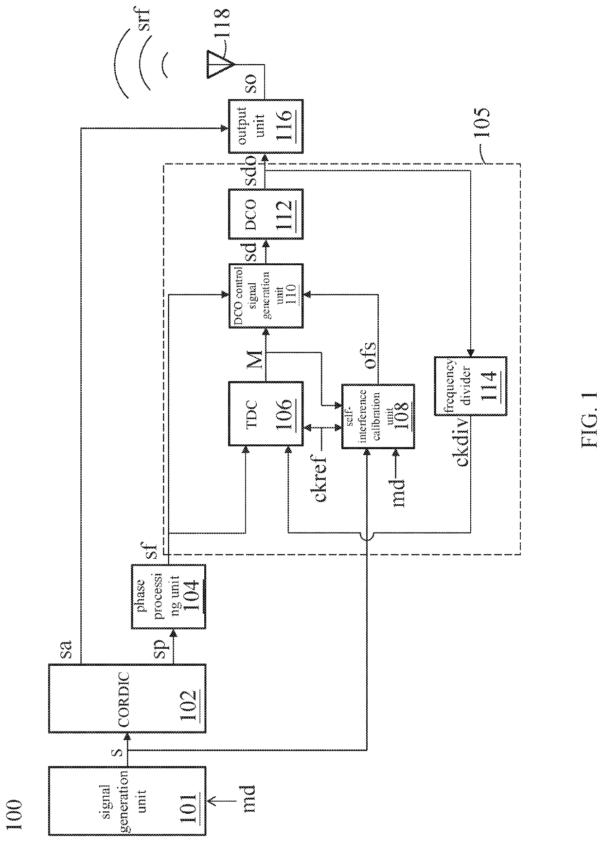
[0014]FIG. 1 is a schematic diagram illustrating a transmitter with self-interference calibration ability according to the present application. The transmitter 100 adopts the polar transmitter architecture in combination with a digital phase-locked loop (DPLL) 105, a signal generation unit 101 configured to generate an IQ signal s, a coordinate rotation digital computer (CORDIC) 102 configured to generate an amplitude modulation signal sa and a phase modulation signal sp according to the IQ signal s, wherein the phase modulation signal sp generates a frequency signal sf after passing through a phase processing unit 104, and the DPLL 105 generates a DCO output signal sdo according to a frequency signal sf and a reference clock ckref, wherein the reference clock ckref is generated by a crystal oscillator (not shown in the drawings); an output unit 116 synthesizes an output signal so according to the amplitude modulation signal sa and the DCO output signal sdo, and then an antenna 118 ...


PUM


Abstract

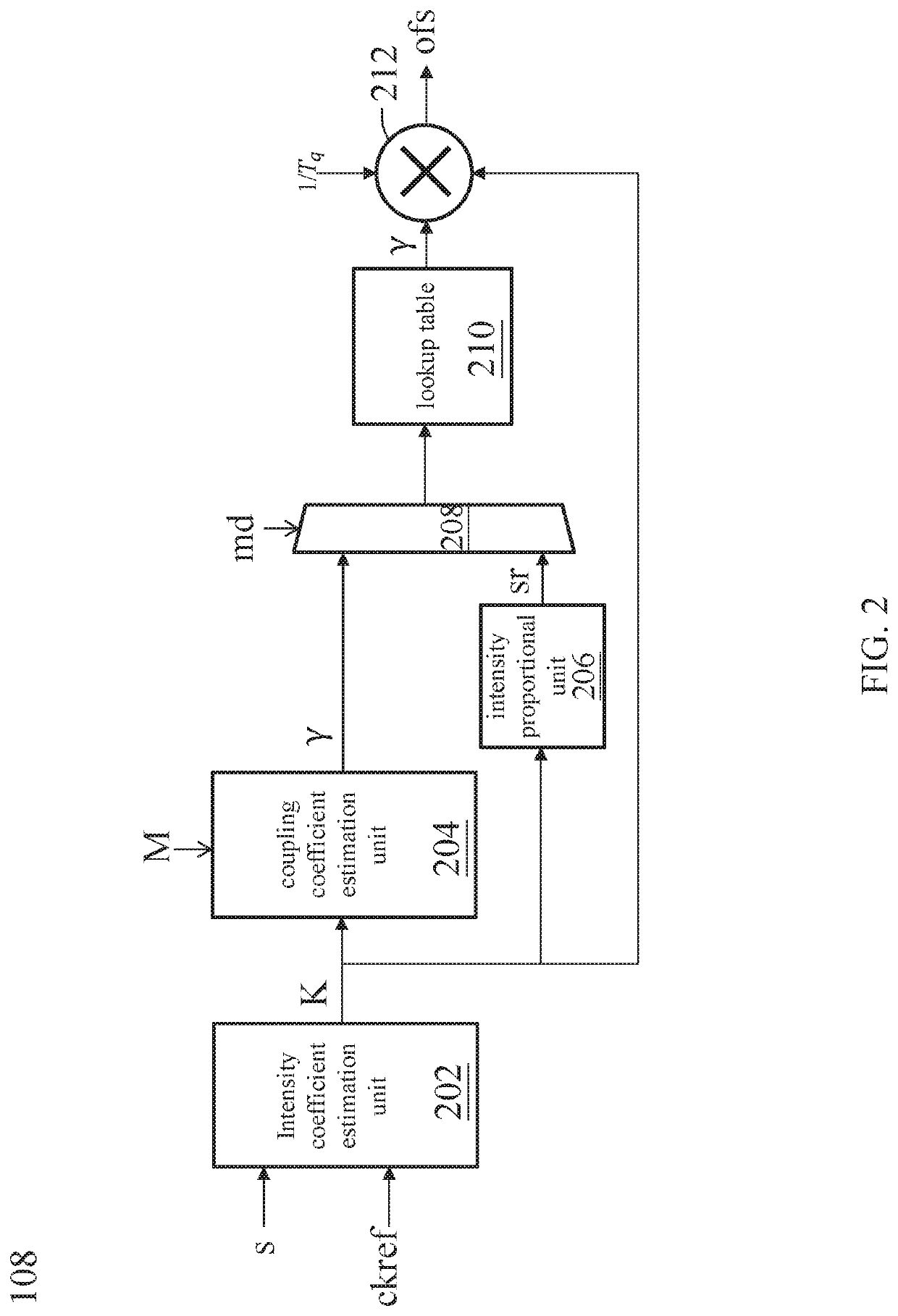
The application discloses a transmitter with self-interference calibration ability, including: a signal generation unit for generating a signal; a CORDIC for generating an amplitude modulation signal and a phase modulation signal according to the signal; phase processing unit, for generating a frequency signal according to the phase modulation signal; a DPLL, including: a DCO, self-interference calibration unit, for generating phase compensation according to the signal, a phase difference and a reference clock; and a DCO control generation unit; and an output unit; for generating an output signal according to the amplitude modulation signal and a DCO output signal.

Description

CROSS REFERENCE TO RELATED APPLICATIONS[0001]This application claims priority of Taiwan application No. 109112689 filed on Apr. 15, 2020, which is incorporated by reference in its entirety.TECHNICAL. FIELD[0002]The present application relates to a transmitter; in particular, to a transmitter with self-interference calibration ability transmitter and a related method.BACKGROUND[0003]For modern wireless communication systems, the polar transmitter architecture is quite competitive because it has smaller area and less power consumption, compared to the traditional analog architecture. Polar transmitter architecture, when used in connection with a digital phase-locked loop (DPLL) with two-point modulation or three-point modulation can increase the bandwidth of polar transmitters; however, it comes with the disadvantage that the transmitted signal may interfere with the crystal oscillator supplying the DPL; this self-interference phenomenon will increase the jitter of the output clock of...

Claims


Application Information

Patent Timeline
Patent Type & Authority Applications(United States)
IPC IPC(8): H04B1/04H03L7/099H04L7/033
CPCH04B1/0475H04L7/0331H03L7/0991H04B17/11H04L27/36H03L2207/50
Inventor WANG, CHIH-CHIEH
Owner REALTEK SEMICON CORP
Learn More