Method and device for transmitting uplink control signal in wireless communication system
a wireless communication system and control signal technology, applied in signal allocation, digital transmission, transmission path sub-channel allocation, etc., can solve the problems of weak self-interference, dl transmission quality and ul transmission quality may not be guaranteed, and overall frequency efficiency declines, so as to reduce self-interference, reduce the influence of self-interference, and improve communication system performance
- Summary
- Abstract
- Description
- Claims
- Application Information
AI Technical Summary
Benefits of technology
Problems solved by technology
Method used
Image
Examples
first embodiment
ency Band
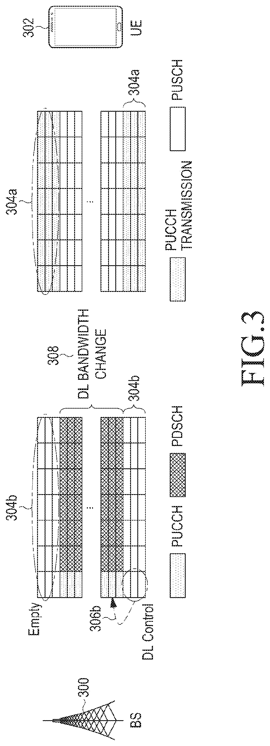
[0038]A first embodiment of the present disclosure proposes a method for protecting a PUCCH control signal when one frequency band is used. More specifically, the first embodiment includes 1) a method for changing a bandwidth of a DL to protect a PUCCH control signal and 2) a method for changing a transmission format of a PUCCH to protect a PUCCH control signal.
[0039]1) Method for Changing a DL Bandwidth
[0040]In an embodiment of the present disclosure, to reduce self-interference occurring in transmission of a PUCCH control signal based on full-duplex communication, a frequency bandwidth allocated for a DL is reduced and DL transmission is performed in an entire frequency domain allocated to a system. FIG. 3 illustrates an example of a method for changing a DL bandwidth according to an embodiment of the present disclosure. Referring to FIG. 3, in an embodiment of the present disclosure, a BS 300 performs DL transmission through a remaining frequency band 308 while vacating ...
second embodiment
e Frequency Bands
[0062]Hereinbelow, a second embodiment of the present disclosure proposes a method for protecting a PUCCH control signal when one or more frequency bands are used. FIG. 8A is a flowchart illustrating an operation of protecting an UL control signal when one or more frequency bands are used according to a second embodiment of the present disclosure. For convenience, as a detailed example, a system to which the second embodiment of the present disclosure is applied is assumed to use two frequency bands.
[0063]Referring to FIG. 8A, in operation 804, a BS 802 determines to perform full-duplex communication and notifies a UE 800 that full-duplex communication is to be performed. In operation 806, the BS 802 determines a frequency band allocated to an UL control channel between two operating frequency bands, for example, a partial band of a second frequency band, and transmits information about the determined frequency band to the UE 800 through high-layer signaling. In ope...
third embodiment
ich a PUSCH Control Signal is Transmitted Using a PUCCH
[0066]In a PUSCH, UL data and an UL control signal are transmitted together and thus it is difficult to protect only a control signal from self-interference. Therefore, a third embodiment of the present disclosure proposes a scheme for protecting a control signal by transmitting a control signal transmitted in the PUSCH through a PUCCH.
[0067]FIG. 9A is a flowchart illustrating an operation of transmitting a PUSCH control signal through a PUCCH according to an embodiment of the present disclosure.
[0068]Referring to FIG. 9A, a BS 902 having determined full-duplex communication transmits transfer information instructing the UE 900 to perform transmission of a PUSCH control signal through a PUCCH when sending a CSI request to a UE 900 in operation 904. Then, in operation 906, the UE 900 having received the transfer information transmits PUSCH control signal by using the PUCCH. FIG. 9B shows an example of a scheme in which a PUSCH co...
PUM
 Abstract
Description
Claims
Application Information
 - R&D
- Intellectual Property
- Life Sciences
- Materials
- Tech Scout
- Unparalleled Data Quality
- Higher Quality Content
- 60% Fewer Hallucinations
Browse by: Latest US Patents, China's latest patents, Technical Efficacy Thesaurus, Application Domain, Technology Topic, Popular Technical Reports.
© 2025 PatSnap. All rights reserved.Legal|Privacy policy|Modern Slavery Act Transparency Statement|Sitemap|About US| Contact US: help@patsnap.com


