

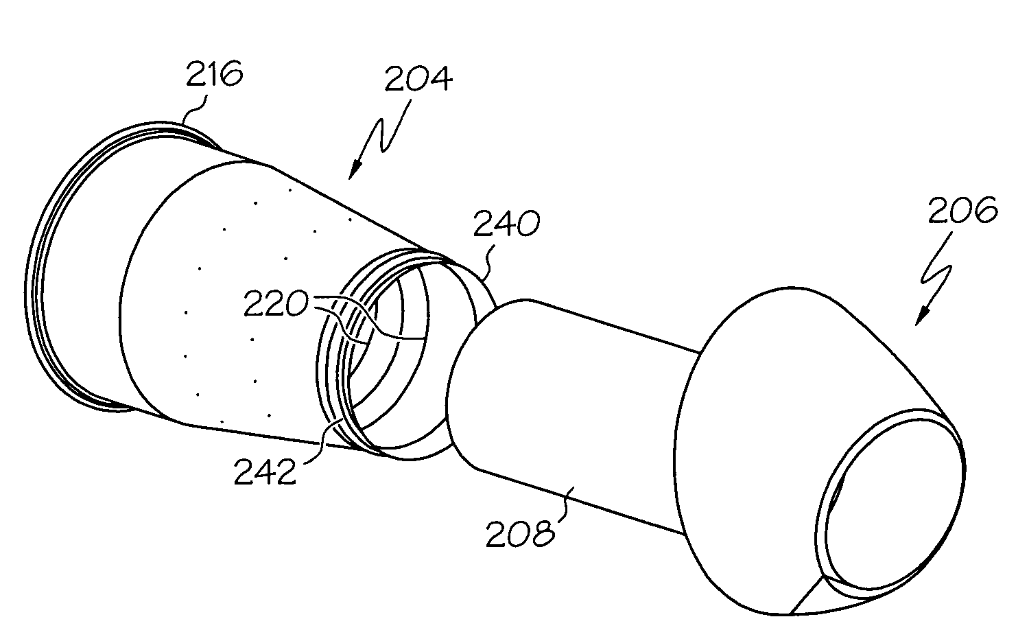
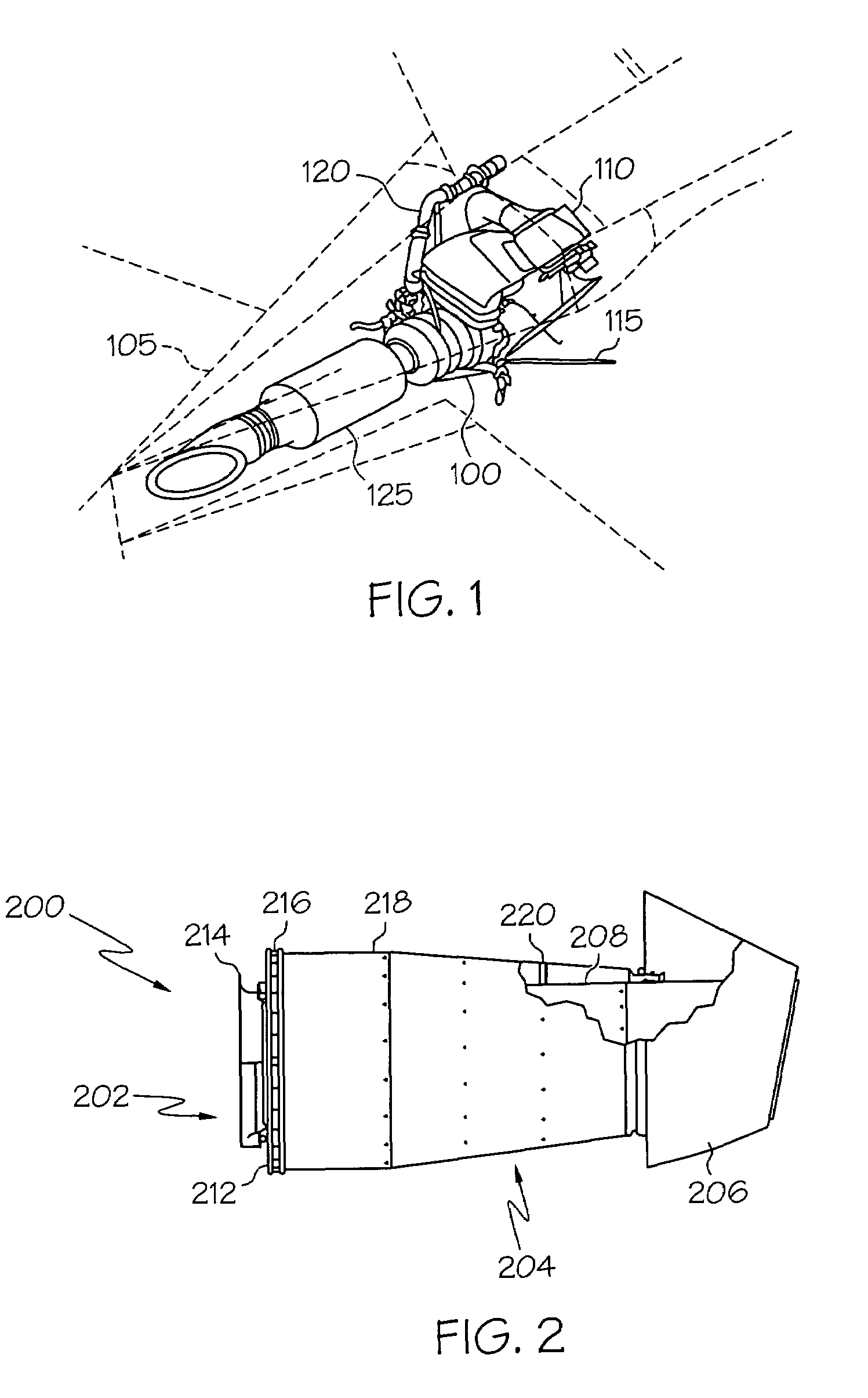
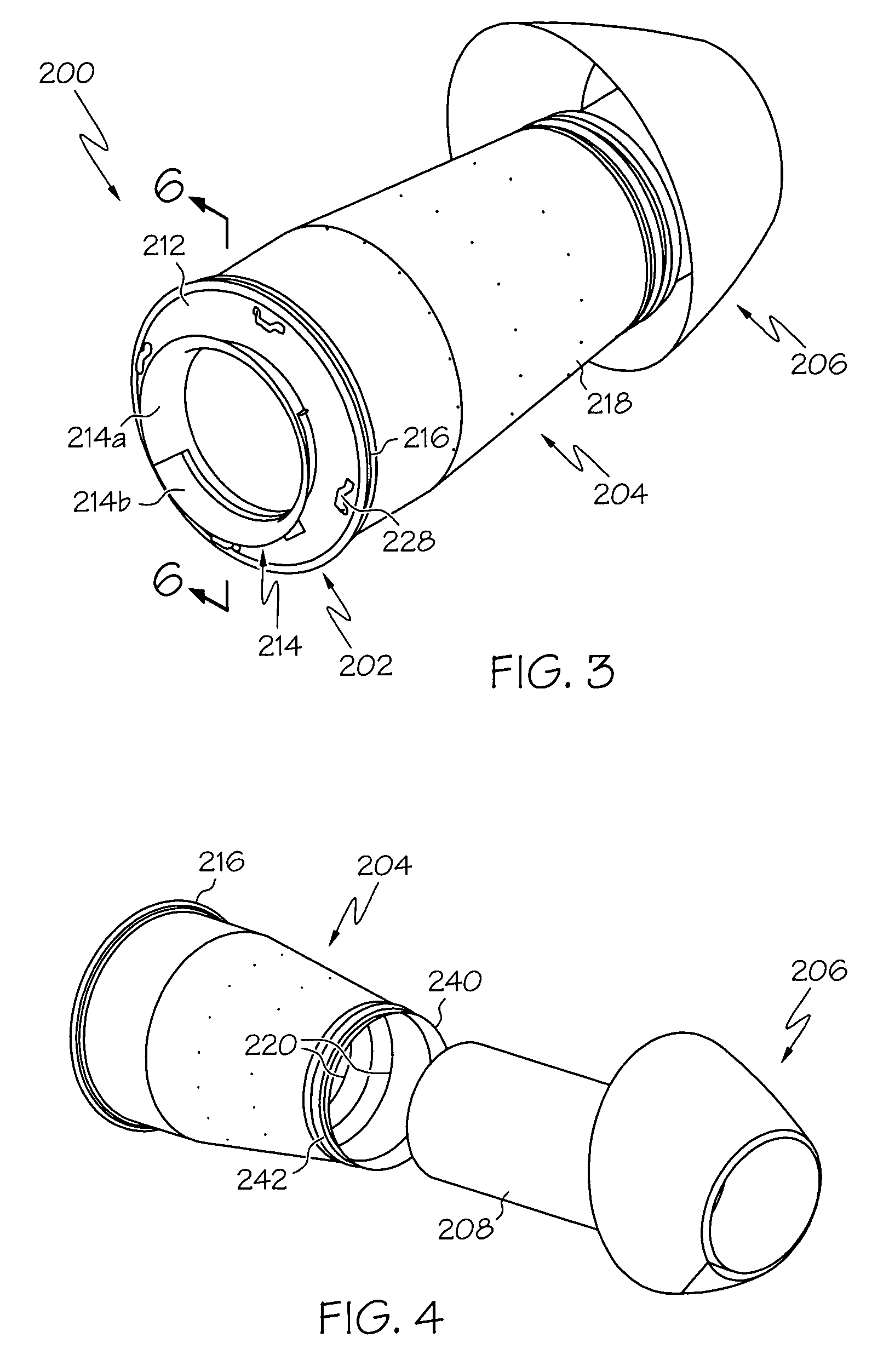
Auxiliary power unit exhaust duct with muffler incorporating an externally replaceable acoustic liner
a technology of external replacement and exhaust duct, which is applied in the direction of air-flow influencers, instruments, heat measurement, etc., can solve the problems of brittleness and cracking the design of the exhaust duct may not lend itself to simple and straightforward repair methods for replacing the acoustic liner
- Summary
- Abstract
- Description
- Claims
- Application Information
AI Technical Summary
Benefits of technology
Problems solved by technology
Method used
Image

Examples
Embodiment Construction
[0020]The following detailed description of the invention is merely exemplary in nature and is not intended to limit the invention or the application and uses of the invention. Furthermore, there is no intention to be bound by any expressed or implied theory presented in the preceding technical field, background, brief summary or the following detailed description.
[0021]As used herein, the terms “comprises,”“comprising,”“includes,”“including,”“has,”“having” or any other variation thereof, are intended to cover a non-exclusive inclusion. For example, a process, method, article, or apparatus that comprises a list of elements is not necessarily limited to only those elements but may include other elements not expressly listed or inherent to such process, method, article, or apparatus. Further, unless expressly stated to the contrary, “or” refers to an inclusive or and not to an exclusive or. For example, a condition A or B is satisfied by any one of the following: A is true (or present...
PUM
 Abstract
Description
Claims
Application Information