Front vehicle body structure

a front and rear body technology, applied in the direction of roofs, jet propulsion mounting, transportation and packaging, etc., can solve the problem of not being appropriately absorbed by only the compression or squashing of the left and righ

Inactive Publication Date: 2008-07-01
HONDA MOTOR CO LTD
View PDF17 Cites 121 Cited by
  • Summary
  • Abstract
  • Description
  • Claims
  • Application Information

AI Technical Summary

Benefits of technology

[0006]In view of the foregoing prior art problems, it is an object of the present invention to provide an improved front vehicle body structure which can reliably absorb an impact load before the engine-transmission unit hits the left and right front side frames.
[0007]In order to accomplish the above-mentioned object, there present invention provides an improved front vehicle body structure, which comprises: a vehicle body frame including left and right front side frames; a subframe provided on the underside of the vehicle body frame and supporting an engine-transmission unit; an impact absorbing section formed by respective rear half portions of the two front side frames extending toward the rear of the vehicle body while gradually approaching the centerline of the vehicle body, the impact absorbing section preventing the engine-transmission unit from being displaced toward the rear of the vehicle body when a load has been applied from front ends of the left and right front side frames toward the rear of the vehicle body; and left and right mounting brackets provided, on the respective rear half portions of the left and right front side frames forming the impact absorbing section, to project toward the centerline of the vehicle body, the left and right mounting brackets being detachably connected to the subframe. When an impact load has been applied to the left and right front side frames, the left and right mounting brackets are detached from the subframe, and then the detached left and right mounting brackets are compressed or squashed by the engine-transmission unit while absorbing the impact.
[0008]When a relatively great impact load has been applied rearwardly to the front ends of the left and right front side frames, the left and right mounting brackets in the present invention are detached from the subframe, and then the detached left and right mounting brackets are compressed or squashed by the engine-transmission unit. The applied impact load can be sufficiently absorbed by the left and right mounting brackets being squashed by the engine-transmission unit. After that, the engine-transmission unit abuts against the rear half portions of the left and right mounting brackets. Namely, with the provision of the left and right mounting brackets, the impact load can be reliably absorbed before the engine-transmission unit abuts against the rear half portions of the left and right front side frames. Therefore, it is not necessary to enhance more than necessary the rigidity of the engine-transmission unit and left and right front side frames.
[0010]Further, it is preferable that, as viewed in plan, the left and right mounting brackets each have a generally U plane cross-sectional shape such that the two mounting brackets are opposed to each other with the centerline of the vehicle body therebtween. Such arrangements allow the left and right mounting brackets to be squashed by the engine-transmission unit in a gradual manner, with the result that the impact load can be reliably absorbed.

Problems solved by technology

However, if the impact load F is relatively great, it may not be appropriately absorbed by only the compression or squash of the left and right front side frames 101 and 102.

Method used


Image

  • Front vehicle body structure
  • Front vehicle body structure
  • Front vehicle body structure

Examples


Embodiment Construction

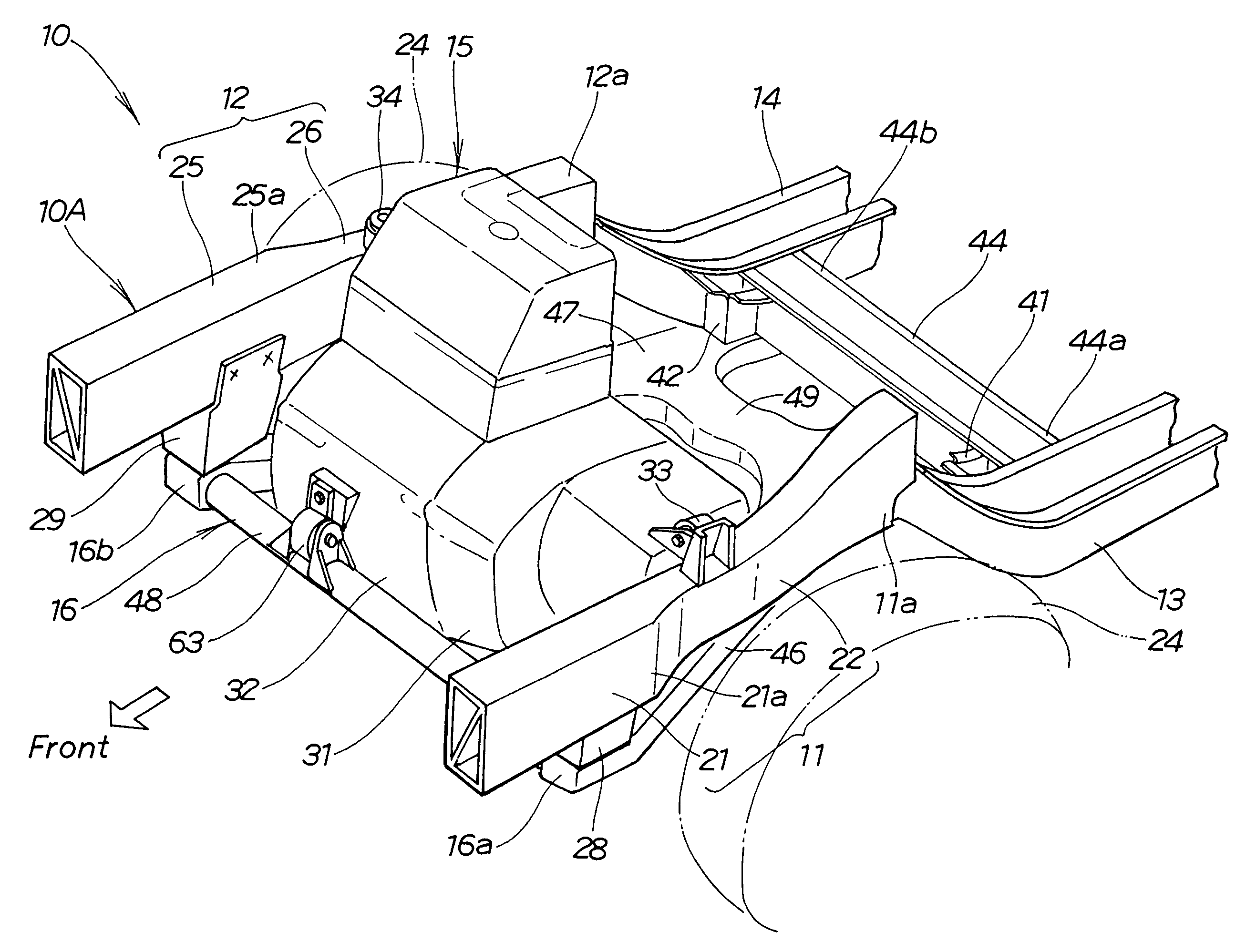
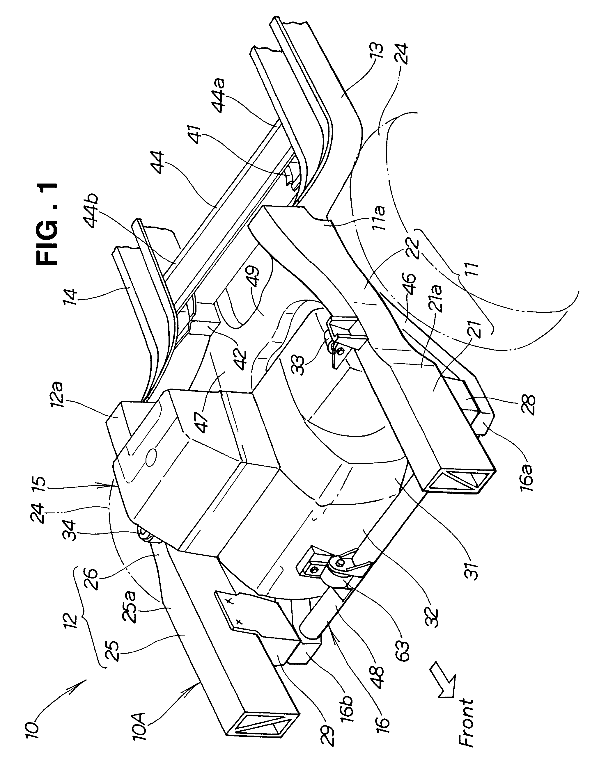
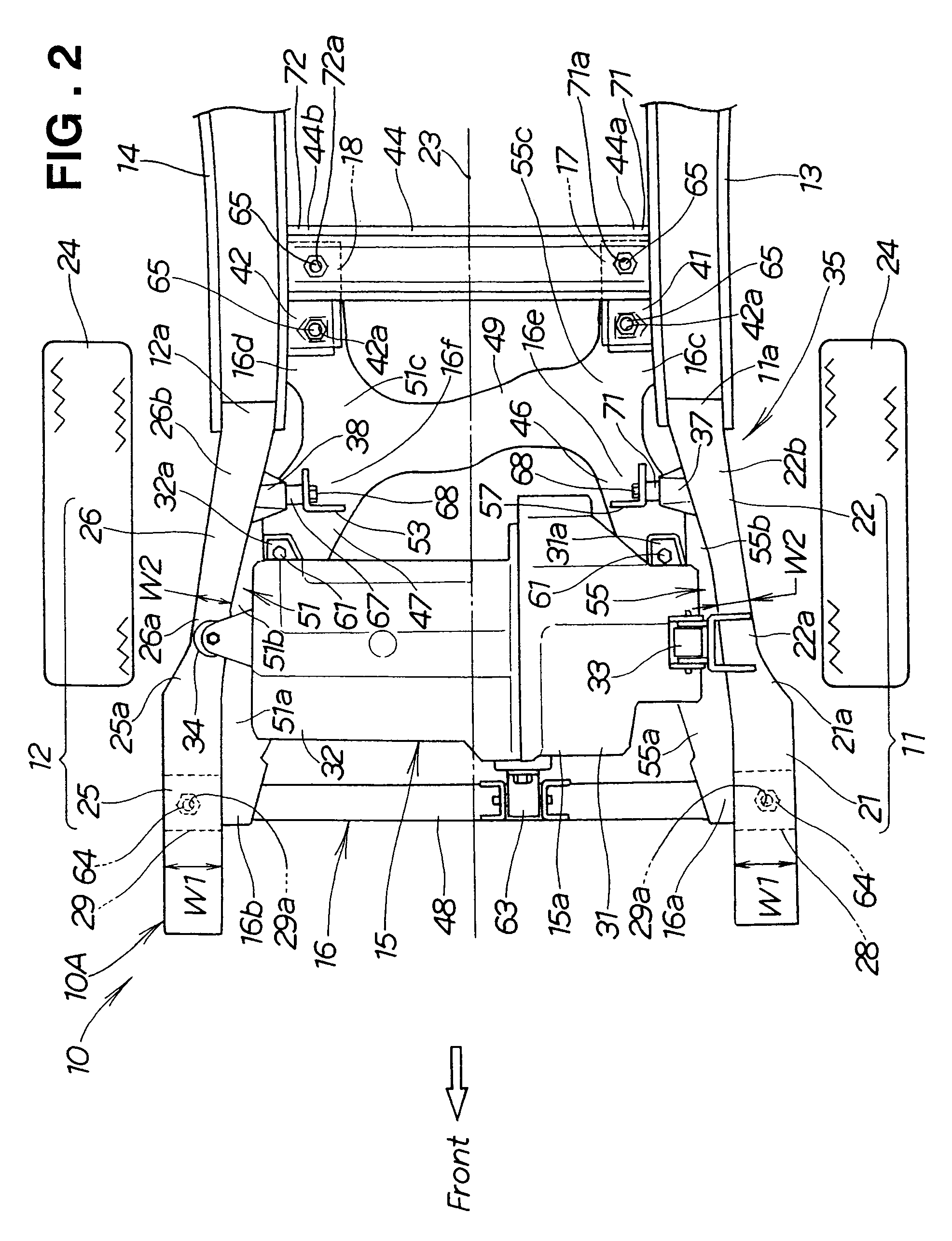
[0025]FIG. 1 is a perspective view of a front vehicle body structure in accordance with an embodiment of the present invention, FIG. 2 is a plan view of the front vehicle body structure, and FIG. 3 is a sectional view of the front vehicle body structure. As seen in FIGS. 1, 2 and 3, the front vehicle body structure 10 of the present invention includes a front vehicle body frame 10A. The front vehicle body frame 10A includes left and right front side frames 11 and 12 that extend in a length or forward / rearward direction of the vehicle and are spaced apart from each other in a width direction of the vehicle.

[0026]Left floor frame 13 extends rearwardly from the rear end 11a of the left front side frame 11, and a right floor frame 14 extends rearwardly from the rear end 12a of the right front side frame 12.

[0027]Engine-transmission unit 15 is disposed transversally between the left and right front side frames 11 and 12.

[0028]Front subframe 16 is fixed to the undersides of the left and r...


PUM


Abstract

Front vehicle body structure includes left and right front side frames, a subframe provided on the undersides of the side frames, and left and right mounting brackets for connecting the side frames and subframe. Engine-transmission unit is mounted on the subframe. Respective rear half portions of the side frames extend toward the rear of the vehicle body while gradually approaching the centerline of the vehicle body. Left and right mounting brackets are provided, on the respective rear half portions, to project toward the centerline. The left and right mounting brackets are detachably connected to the subframe. When an impact load greater than a predetermined intensity has been applied, the left and right mounting brackets are detached from the subframe and then squashed by the engine-transmission unit while effectively absorbing the impact.

Description

FIELD OF THE INVENTION[0001]The present invention relates generally to front vehicle body structures and more particularly to an improved front vehicle body structure including left and right front side frames and having an engine-transmission unit mounted between the side frames.BACKGROUND OF THE INVENTION[0002]From Japanese Patent No. 3226896, for example, there is known a front vehicle body structure for motor vehicles, where left and right front side frames 101 and 102 have their respective rear half portions that are bent relative to their front half portions toward each other, i.e. inwardly in a width direction of the vehicle, to prevent an engine-transmission unit from being accidentally displaced into a vehicle compartment.[0003]The front vehicle body structure disclosed in the 3226896 patent will be described with reference to FIG. 13 hereof. The disclosed front vehicle body structure 100 includes left and right front side frames 101 and 102 disposed in a front section of t...

Claims


Application Information

Patent Timeline
Patent Type & Authority Patents(United States)
IPC IPC(8): B62D21/00
CPCB62D25/08B62D21/155
Inventor MITSUI, JUNTSUJINO, GOROYASUHARA, SHIGETO
Owner HONDA MOTOR CO LTD
Why Eureka
Try Eureka